External I/O Wiring Method
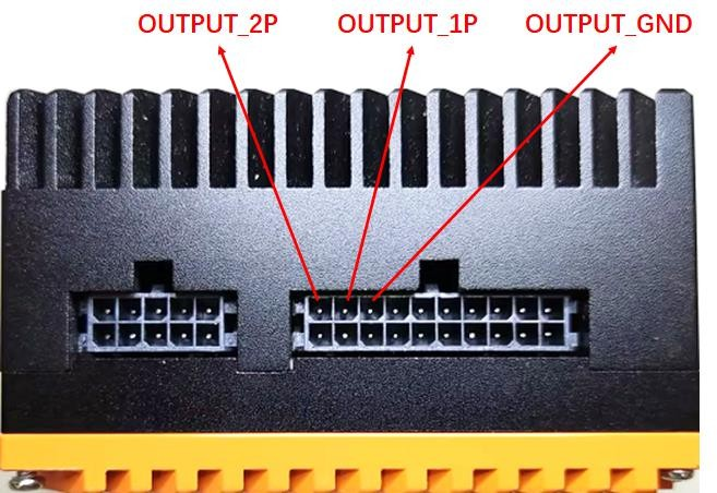
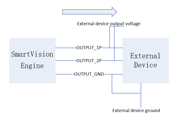
Optocoupler output signal


OUTPUT_1P and OUTPUT_2P are two output signals, OUTPUT_GND is the common ground of the two output signals, and the output voltage of the external device should not exceed 80V.
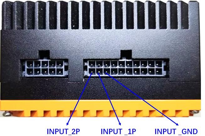
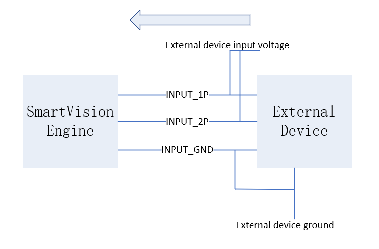
Optocoupler input signal


INPUT_1P and INPUT_2P are two input signals, and INPUT_GND is the common ground of the two input signals. The external input voltage range is 5~20V, 10V is recommended. If you need to change the input voltage range, you can connect series resistors to the external device INPUT_1P and INPUT_2P signals according to specific needs.