I/O Introduction
I/O Electrical Characteristics
The smart camera device is an optocoupler isolated input/output. The input current of the optocoupler device is 5~50ma, with a typical value of 20ma. (It is recommended that the input current is 20ma to achieve the best optocoupler input performance.) The output voltage of the optocoupler device does not exceed 80V. The figure below shows the test circuit for the response time of the optocoupler device.

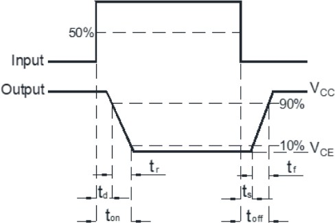
Test environment: VCC=5V, IC=2mA, RL=100Ω
Response Time (Rise): tr typical value 4us, maximum value 18us
Response Time (Fall): tr typical value 3us, maximum value 18us
I/O Circuit
Two optocoupler output circuits
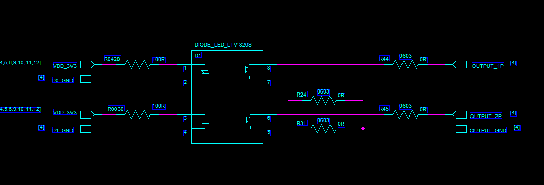
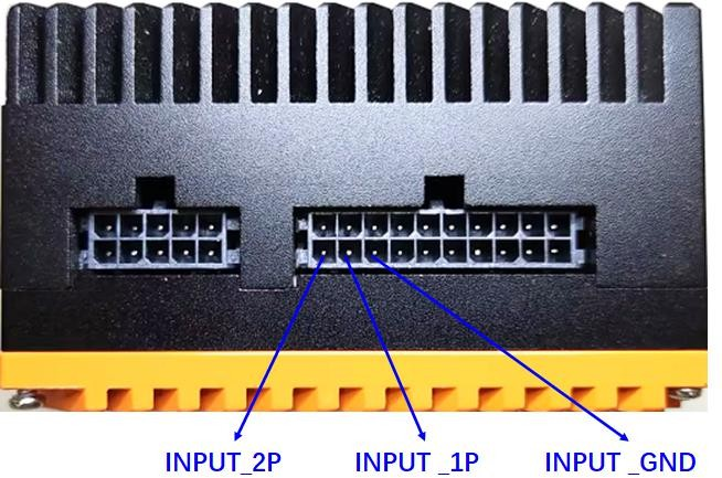
The D1 device is an optocoupler device. The input end of the optocoupler is connected to the smart camera main control, and the output end is connected to the external device through the 20pin connector of the smart camera (that is, the smart camera controls the external device in isolation through the optocoupler device). OUTPUT_1P has been controlled on the smart camera end. The signal current of OUTPUT_2P is 20ma, OUTPUT_1P and OUTPUT_2P are two output signals, and OUTPUT_GND is the common ground of the two output signals.
Two optocoupler input circuits
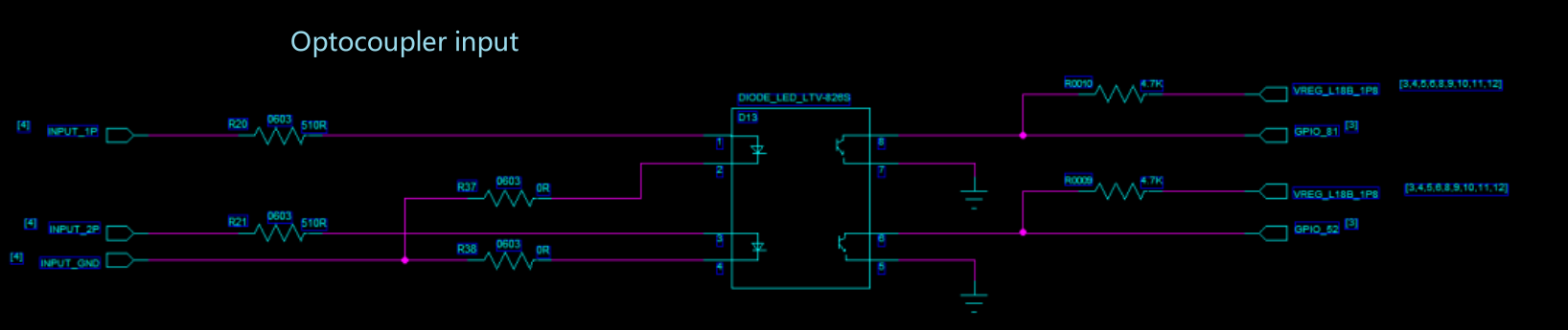
The D13 device is an optocoupler device. The optocoupler input terminal is connected to the external device through the smart camera 20pin connector. The optocoupler output terminal is connected to the smart camera main control (that is, the external device controls the smart camera through optocoupler isolation). INPUT_1P and INPUT_2P are two inputs. signal, INPUT_GND is the common ground of the two input signals.
Note : Since the optocoupler input voltage is determined by the external device, in order to meet the optimal input current of 20ma optocoupler input, the external device can configure the resistance values on the two input signals INPUT_1P and INPUT_2P. Currently, the smart camera is configured with a 510 ohm resistor by default. The voltage range is 5~20V, and the recommended input voltage is 10V. If there is a special voltage input, please ask the external device to configure the resistor by itself.
External I/O Wiring Method
Optocoupler output signal
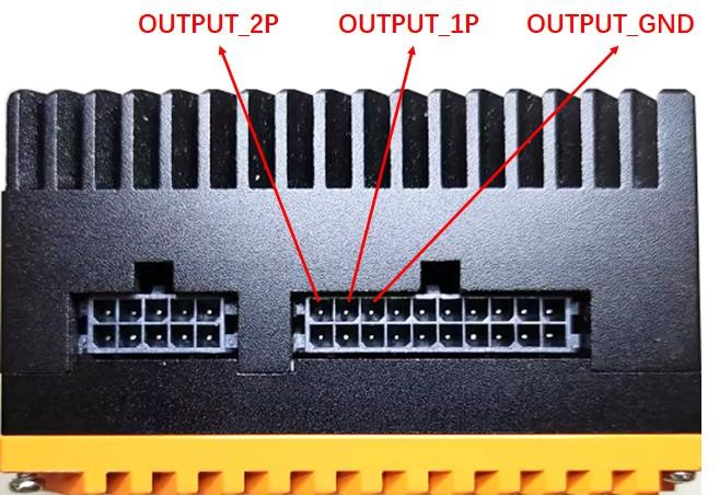
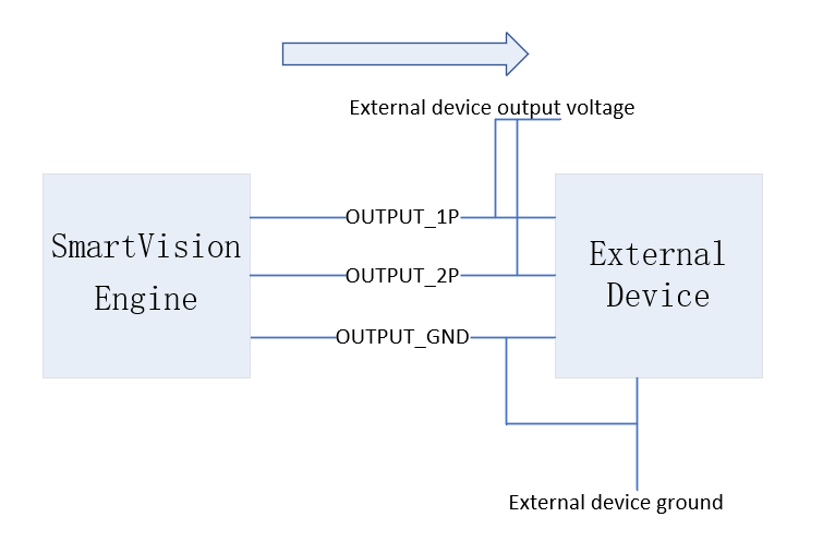
OUTPUT_1P and OUTPUT_2P are two output signals, OUTPUT_GND is the common ground of the two output signals, and the output voltage of the external device should not exceed 80V.
Optocoupler input signal
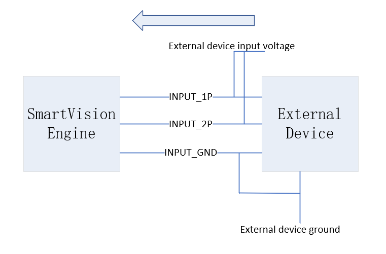
INPUT_1P and INPUT_2P are two input signals, and INPUT_GND is the common ground of the two input signals. The external input voltage range is 5~20V, 10V is recommended. If you need to change the input voltage range, you can connect series resistors to the external device INPUT_1P and INPUT_2P signals according to specific needs.