User Manual for Rhino Pi A1
1. Product Overview
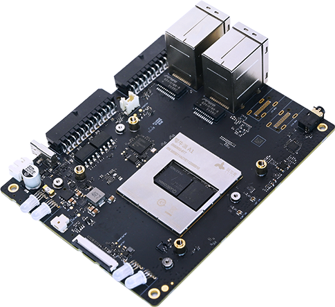
The Rhino Pi A1 is a cost-effective edge computing development board from APLUX, based on the Qualcomm QCS6490 platform, with 12TOPS of AI computing power. The development board offers a rich set of interfaces and supports multiple network connection modes to meet connectivity needs in different application scenarios. It boasts powerful AI capabilities, with a large number of pre-installed scenario-based algorithms and cases covering various fields such as smart parks, smart retail, smart security, transparent kitchen monitoring, and smart transportation, enabling out-of-the-box use. It realizes the intelligent needs of multiple industries and scenarios in a low-cost and high-efficiency manner.
1.1 Product Appearance Diagram
1.2 Product Parameter Table
| Item | Specification |
|---|---|
| Platform | Qualcomm Dragonwing QCS6490 |
| AI Performance | ~12 TOPS INT8 |
| OS | AidLux(Android14 + Ubuntu22.04) |
| CPU | 1xCortexA78 2.7GHz, 3xCortexA78 2.4GHz, 4xCortexA55 1.9GHz, 100k DMIPS,6nm process |
| GPU | Adreno 642, with a computing power of 1100(GFLOPS) |
| RAM | 8GB LPDDR4 |
| Storage | 128GB UFS3.1 |
| Video Codec | Decode: 4K@60fps H.264/H.265 Encode: 4K@30fps H.264/H.265 |
| Camera Module | D-PHY-Camera x1,IMX577(12M) |
| Wireless | Wi-Fi: 802.11ax, 2.4G/5G DBS, 2*2 MIMO BT: 5.1 |
| USB | USB-A3.0:x4,USB-C3.01:x1 Support DP1.4 |
| Audio | 3.5mm:x1 |
| Network Interface | LAN(RJ45)x2,one 2.5Gbps,one 1Gbps |
| Power Supply | DC12V/24V 3A |
| Operating Temperature | -20℃ ~ +70℃ |
| Dimensions | 100x130x39.25mm |
2. Quick Start
2.1 Environment Preparation
2.1.1 Hardware Preparation
- A computer with Windows 10 or later installed
- Rhino Pi A1
- USB Type-A to Type-C data cable
- Power adapter (12V 3A)
2.1.2 Software Preparation
Please refer to the Tool Installation chapter to install the necessary tools to assist developers in using APLUX hardware products.
2.2 Powering On the Device
2.2.1 Connecting the Power Cable
- Use a DC12V3A power adapter to connect to the DC port of the board, which will power on automatically by default. When powering on, observe that the PWR light flashes green (during startup) until both the PWR light and CAM light stay on steadily (startup completed).
2.2.2 Connecting the Type-C Cable
Connect the Type-A end of the cable to the USB3.0 port on the Windows computer; connect the Type-C end of the cable to the Type-C port on the development board.
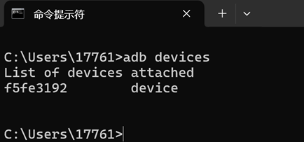
On the Windows computer, press win+R, type "cmd" in the pop-up window to open the terminal window, and enter the following command in the window:
adb devices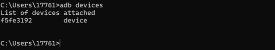
As shown in the figure above, once the device is detected, it indicates that the device is connected and has been successfully powered on. Then, developers can access the AidLux system of the development board according to specific development environment scenarios.
3. Obtaining an IP Address
3.1 Configuring a Dynamic IP Address
When there is a local area network in the developer's working environment, and a DHCP server exists in the local area network to assign DHCP IPs to downstream devices, you can obtain a dynamic IP address by following these steps.
The Rhino Pi A1 device is set to use a DHCP IP by default, so it can obtain an IP address once it is powered on and a network cable is connected to any network port. On the Windows computer, press win+R, type "cmd" in the pop-up window to open the terminal window, and enter the following command in the window:
- Enter "adb shell" to access the host system.
adb shell- Execute the command: "ifconfig eth0" to check the displayed IP address.
ifconfig eth0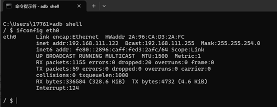
3.2 Configuring a Static IP Address
The Rhino Pi A1 supports configuring a static IP address. Developers can follow these steps to configure it:
- If the network cable is plugged into the eth1 port, set a static IP for eth1. On the Windows computer, press win+R, type "cmd" in the pop-up window to open the terminal window, and execute the following command:
adb shell
am broadcast -a a.e.c --es eth1 ia:s,ip:192.168.1.110,sm:24,gw:192.168.1.1,dns1:114.114.114.114,dns2:8.8.8.8
💡Note
1、The IP address and subnet mask set here are for reference only; specific settings should be based on actual circumstances.
2、In an environment without a router that cannot automatically assign IP addresses, it is recommended to delete the entire "gw:192.168.1.1," information during configuration.
3.2.1 Restoring Dynamic IP Settings
- If you want to restore the dynamic IP settings, on the Windows computer, press win+R, type "cmd" in the pop-up window to open the terminal window, and execute the following command:
adb shell
am broadcast -a a.e.c --es eth1 ia:d
3.3 Configuring Wireless WIFI
The Rhino Pi A1 supports connecting to the network via WIFI. When developers want to connect through a local area network WIFI, they can follow these steps:
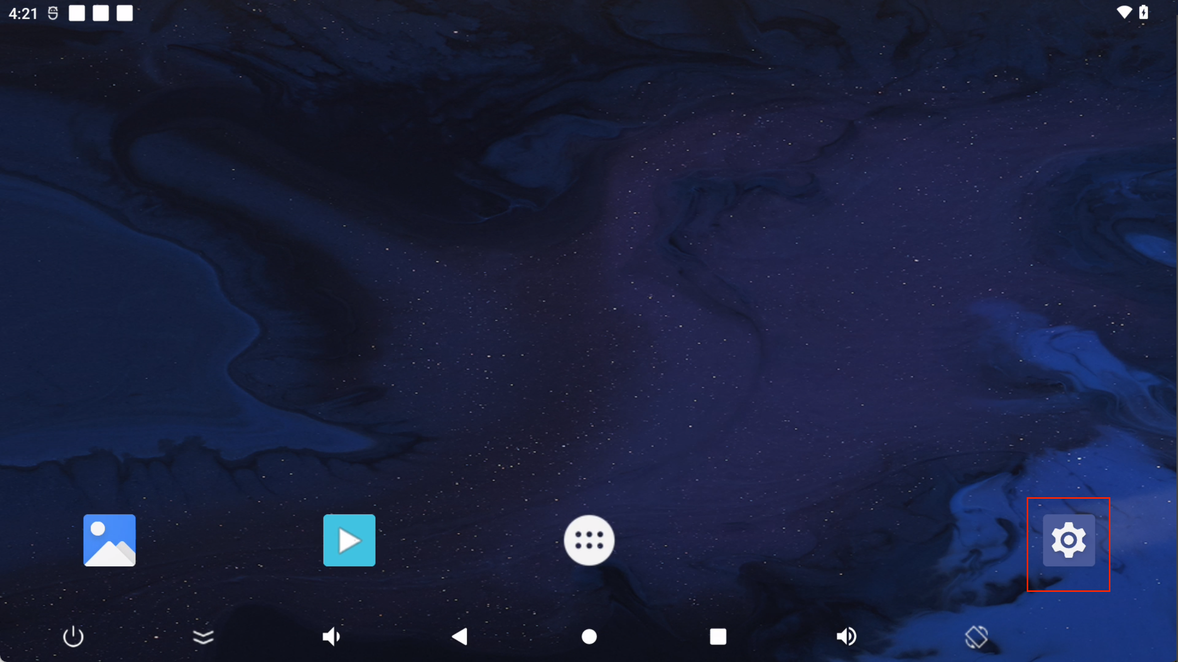
After connecting the Windows computer and the Rhino Pi A1 using a Type-C cable, open the screen mirroring software (QtScrcpy).
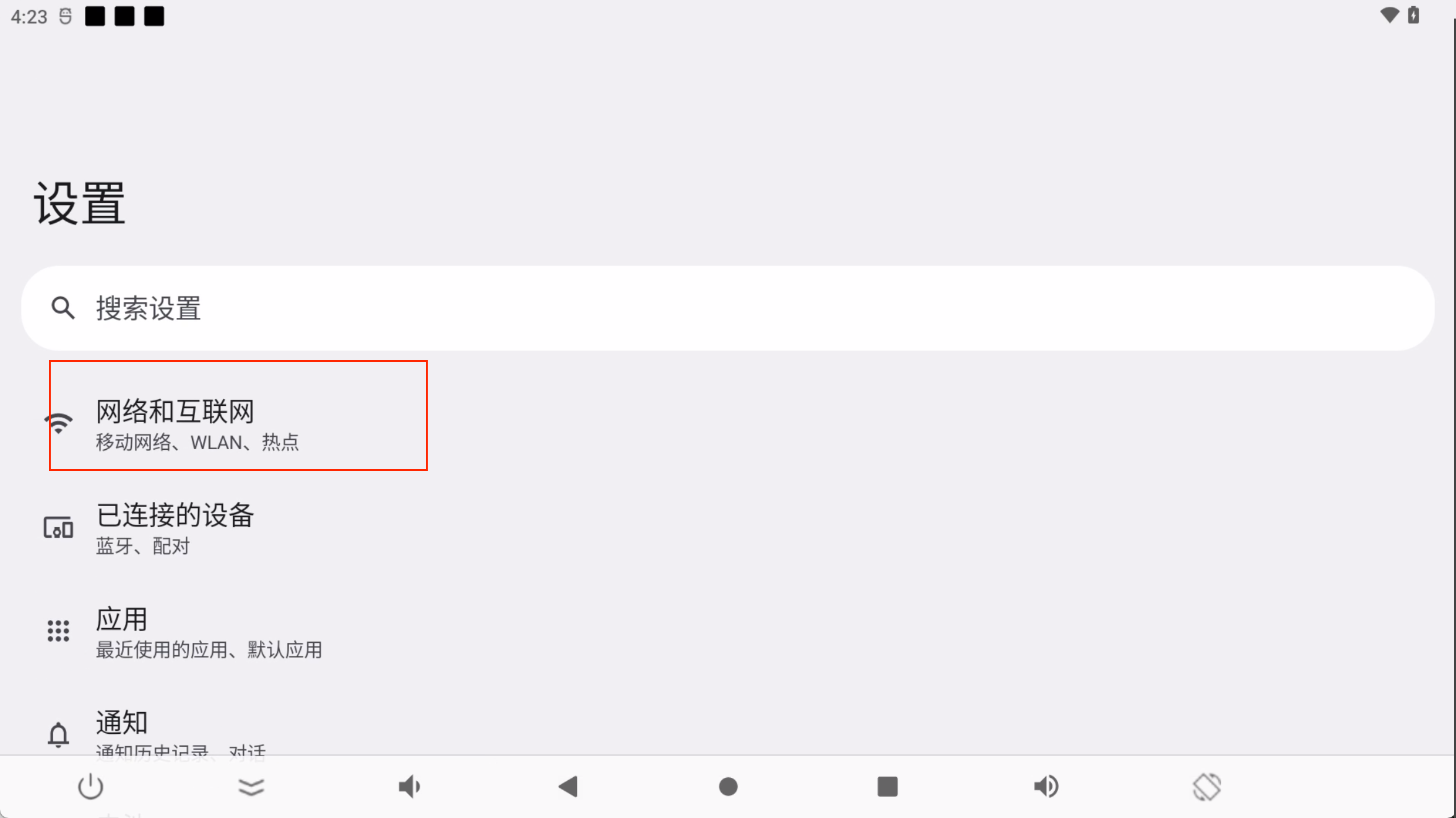
After entering the Android desktop through the screen mirroring software, left-click the "Settings" button with the mouse to open the Android system settings interface.
- Click "Network & internet settings".
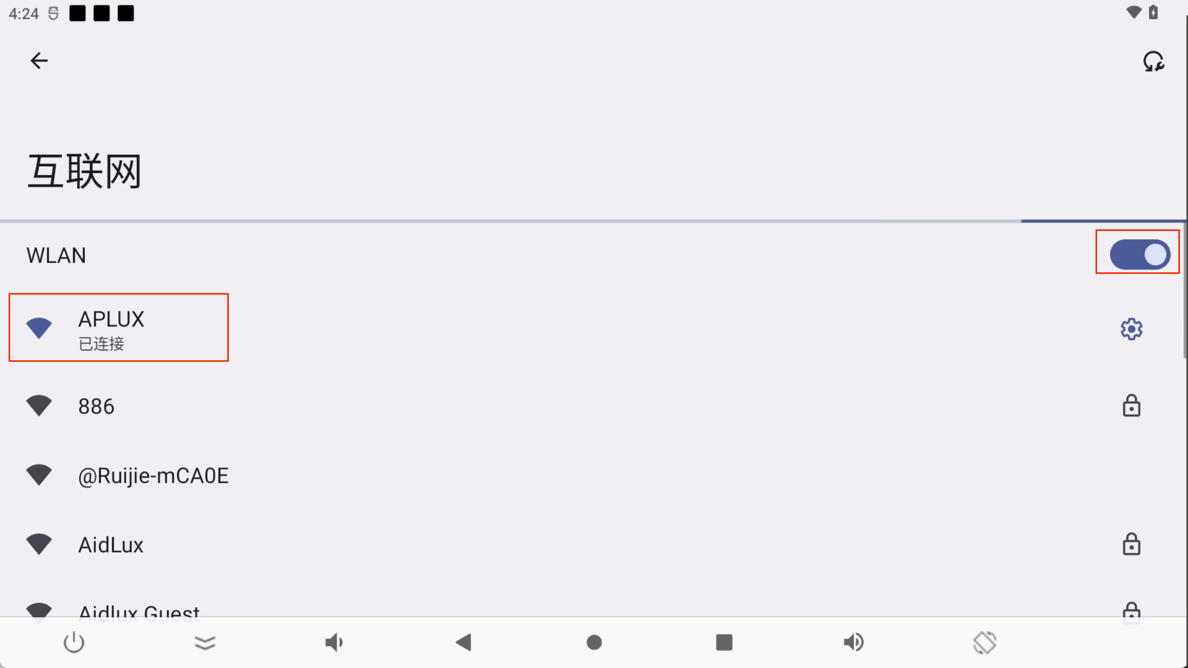
- Click "Internet".

- Open the "WLAN" settings and connect to the corresponding WIFI.
- After waiting for the connection to be completed, execute the command: "ifconfig wlan0" to check the displayed IP address.
adb shell
ifconfig wlan0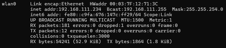
Tip
An antenna needs to be connected to the device when connecting to WIFI.
4. Login to the Aidlux system
For the login method of the integrated system, please refer to the AidLux Login chapter.
5. Description of Internal Onboard Interfaces
- Hardware board interface diagram:


- Hardware board interface correspondence table:
| Interface | Quantity/Specification |
|---|---|
| C-PHY-Camera Module | x 1, IMX586(48M) |
| D-PHY-Camera Module | x 1, IMX577(12M) |
| Binocular Structured Light Camera Module | x 1, IMX577(12M)+2*OV9282(2M) |
| LCD | x 1, MIPI interface, default ST7703,720*1280(customers can customize FPC adapter to improve resolution) |
| USB Type-A | x 4, USB3.0,host mode (total bandwidth of 4 channels supports 5Gbps) |
| USB Type-C | x 1, USB3.0,supports DP1.4 |
| LAN(RJ45) | x 2,one 2.5Gbps,one 1Gbps |
| CAN | x 2 |
| RS232 | x 2,for transmitting serial port information |
| RS485 | x 1,for transmitting serial port information |
| Optocoupler Input | x 2,5~30V |
| Optocoupler Output | x 2,5~30V |
| TF 卡 | x 1 |
| I2S | x 1,3.3V |
| SPI | x 1,3.3V |
| GPIO | x 5,3.3V |
| UART | x 1,3.3V |
| Debug UART | x 1,for debug |
| Headphone | x 1,3.5mm |
| SPK | x 1,1.65W |
| Tri-color LED | x 4,tri-color indicator lights: red, green, blue |
| KEY | x 3,power/vol+/vol- |
| Power Interface 12V/24V | x 1,powered by external adapter |
| RTC | x 1,CR2032(225mAh) |
| ANT | x 2,WIFI/BT antenna |
| Operating Temperature | -30℃~+75°C |
| Storage Temperature | -40°C ~ +90°C |
| Dimensions | 100 x 130 x 39.25mm |
6. File Transfer
6.1 Using SCP for File Transfer
SCP transfer requires the Rhino Pi A1 to be connected to the network normally. You can enter the following command in the terminal to check the IP address:
ifconfig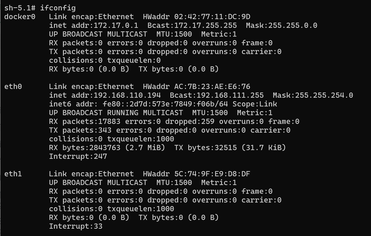
- Use the following command in the PC terminal to upload the file test.txt to the /home/aidlux/ directory.
scp -r .\test.txt aidlux@192.168.110.194:/home/aidlux/- Use the following command in the PC terminal to download the file to the current directory of the PC.
scp -r aidlux@192.168.110.194:/home/aidlux/test.txt ./6.2 Transferring Files Using AidLux File Browser
Transferring files using AidLux File Browser requires the Rhino Pi A1 to be connected to the network normally. If the IP address of the development board is 192.168.110.194, follow these steps to transfer files:
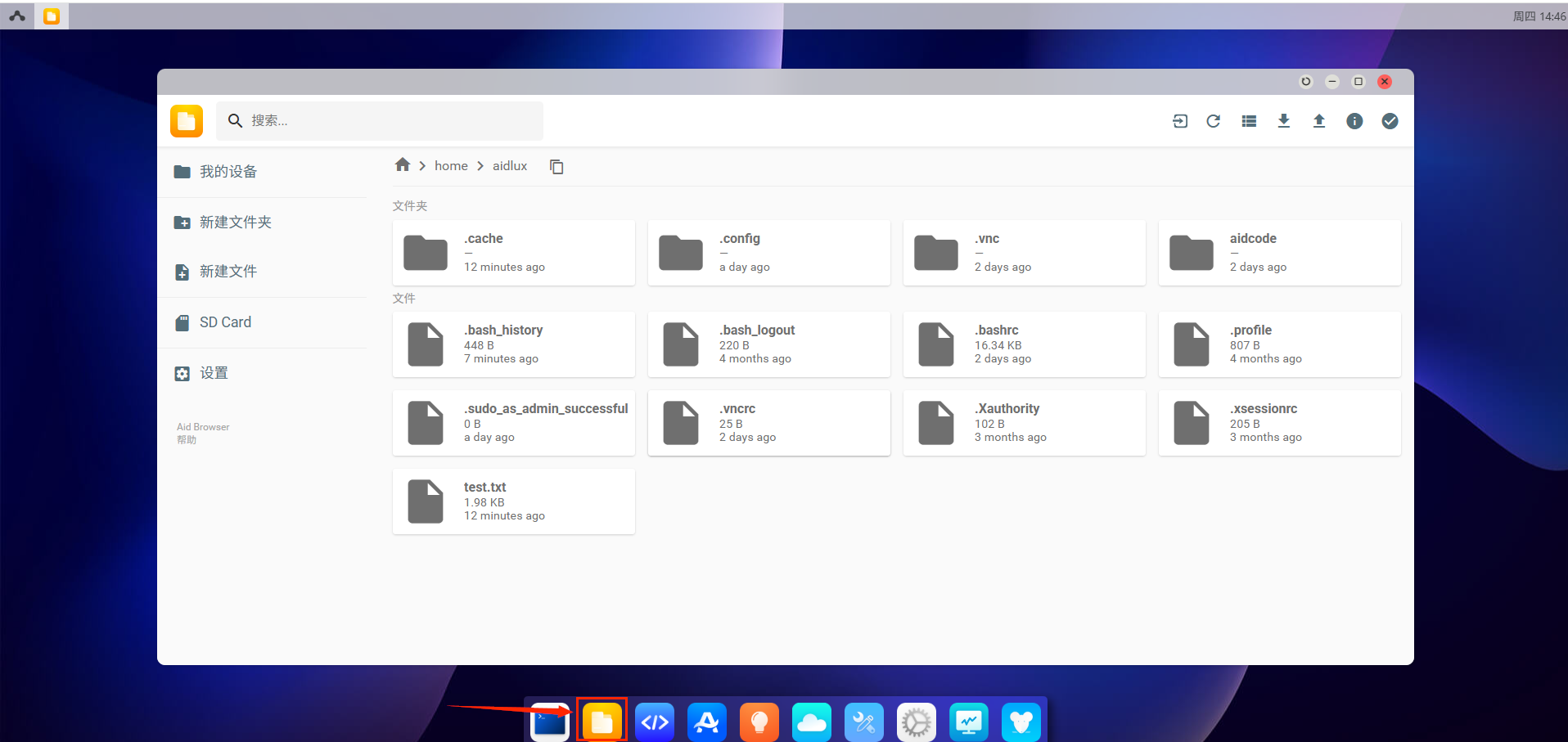
- Enter the URL: http://192.168.110.194:8000/ in the browser to log in to the AidLux desktop environment. The password is: aidlux. After logging in, you can click the File Browser icon to enter.
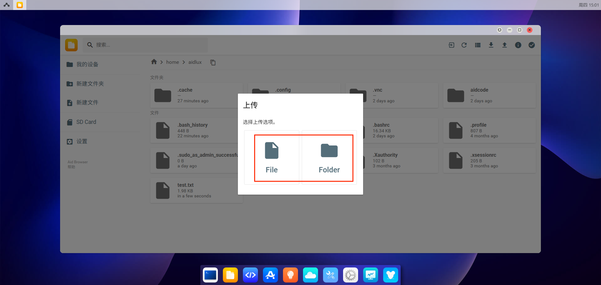
- Click the upload button in the upper right corner to upload files or directories to the /home/aidlux/ directory.
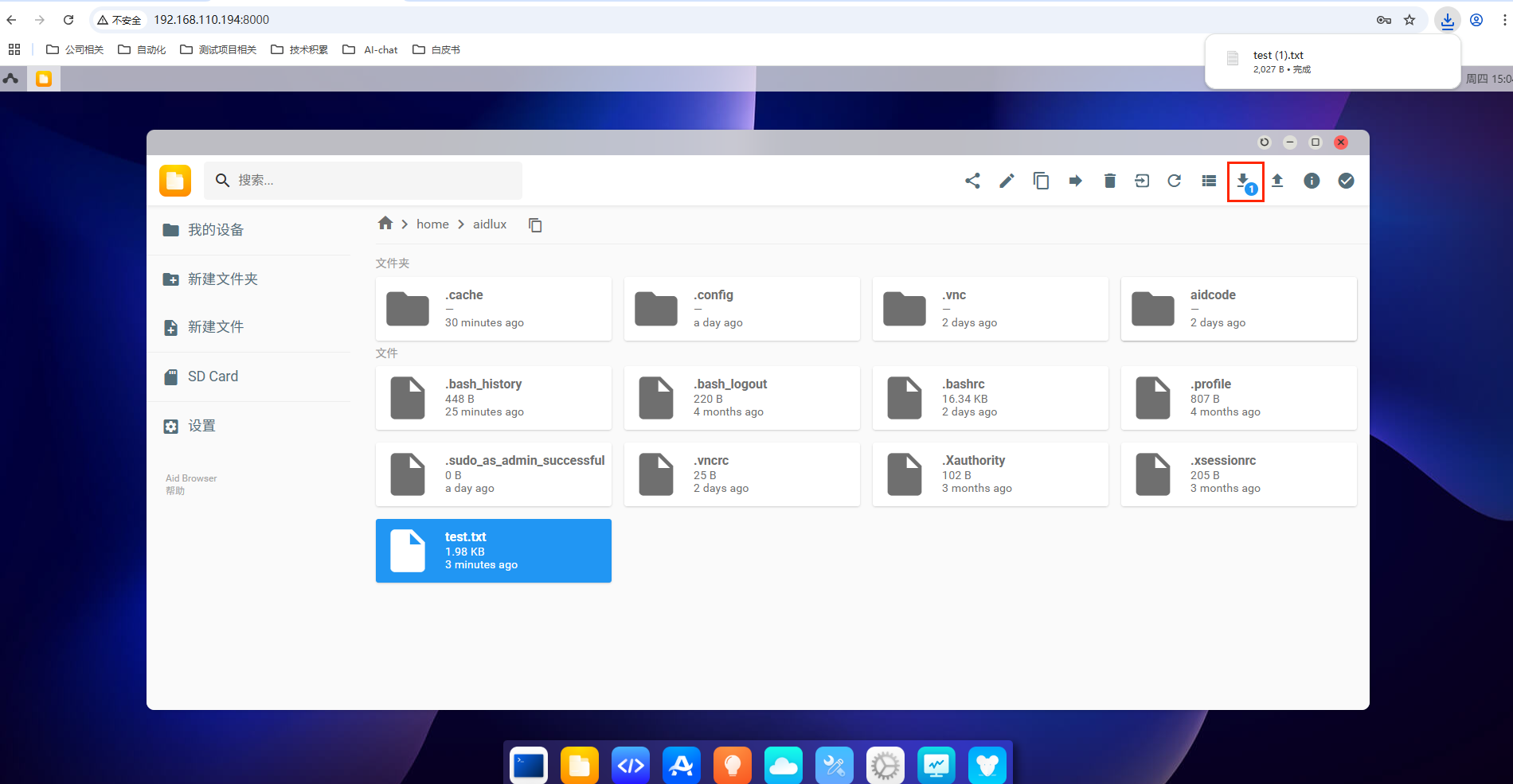
- Click the download button in the upper right corner to download files or directories from the /home/aidlux/ directory to the local computer.
7. Model Plaza
APLUX has built theModel Farm platform. The Model Plaza contains hundreds of mainstream open-source models with different functions, which have been adapted and optimized for different hardware platforms. Developers can quickly complete evaluations on the Rhino Pi A1 without investing a lot of costs and waiting for a long time. For the usage guide of Model Farm, please refer to theModel Farm User Guide document.
8. Usage of AI Functions
APLUX has built a complete edge AI development tool suite to help developers accelerate the deployment of AI applications, covering everything from the underlying system to upper-level application-level SDKs.
or details, please refer to theDeveloper Guide
8.1 Examples of Aidlite SDK Usage
8.1.1 SDK&API Documentation
8.1.2 aidlite_qnn
# Enter the project directory:
cd /usr/local/share/aidlite/examples/aidlite_qnn229/python

# Run the test project script:
sudo python3 qnn_yolov5_multi.py

# Note: 1. A password is required for sudo: aidlux 2. The current example only calls DSP# Enter the project directory:
cd /usr/local/share/aidlite/examples/aidlite_qnn229/cpp
# Compile the executable program:
sudo mkdir build && cd build
sudo cmake ..
sudo make
# Run the test project script:
sudo ./qnn_yolov5_multi 4
# Note: 1. A password is required for sudo: aidlux 2. The current example only calls DSP8.1.3 aidlite_snpe
# Enter the project directory:
cd /usr/local/share/aidlite/examples/aidlite_snpe223/python

# Run the test project script:
sudo python3 snpe2_yolov5_multi.py 3

# Note: 1. A password is required for sudo: aidlux 2. The current example only calls DSP# Enter the project directory:
cd /usr/local/share/aidlite/examples/aidlite_snpe223/cpp
# Compile the executable program:
sudo mkdir build && cd build
sudo cmake ..
sudo make
# Run the test project script:
sudo ./snpe2_yolov5_multi 4
# Note: 1. A password is required for sudo: aidlux 2. The current example only calls DSP8.1.4 aidlite_tflite
# Enter the project directory:
cd /usr/local/share/aidlite/examples/aidlite_tflite/python

# Run the test project script:

# Call the CPU:
sudo python3 tflite_yolov5_multi.py 1

# Call the GPU:
sudo python3 tflite_yolov5_multi.py 2

# Note: 1. A password is required for sudo: aidlux# Enter the project directory:
cd /usr/local/share/aidlite/examples/aidlite_tflite/cpp
# Compile the executable program:
sudo mkdir build && cd build
sudo cmake ..
sudo make
# Run the test project script:
# Call the CPU:
sudo ./snpe2_yolov5_multi 1
# Call the GPU:
sudo ./snpe2_yolov5_multi 2
# Call the DSP:
sudo ./snpe2_yolov5_multi 3
# Note: 1. A password is required for sudo: aidlux8.3 AidCV Usage Examples
8.3.1 AidCV SDK Document
# Enter the project directory:
cd /usr/local/share/aidcv/samples

# Run the test project script to call the local video file:
python3 test_video.py 0

# Note:  When using aidcv, it is necessary to enable the graphical desktop. For example, the pop-up window can only be viewed after executing aidcv on the aidlux desktop.
9. Flash Guide
Tip
Flashing will format the system, so please back up your data in advance before the upgrade.
9.1 Image Download
According to the selection you made when placing the order, APLUX has pre - installed the corresponding system version for the Rhino Pi A1 at the factory to help you quickly conduct the unboxing operation experience (it is not the latest version). If you want to experience other versions, you can select the version you need to download according to the following table.
| Serial Number | Image Name | Version Download Link |
|---|---|---|
| 1 | Rhino Pi A1 ROM | RhinoPi-A1-A14 |
9.2 System Flashing
💡Note
If the current ROM used by your purchased Rhino Pi A1 is Android, then to re-flash the system, you only need to perform the step 9.2.8 of system downloading, and there is no need to perform the two steps of 9.2.6 full erasure and 9.2.7 engineering mode.
9.2.1 Switch to flashing mode
After the device is powered on, use a USB-Type-C cable to connect the computer and the device. Connect the USB end to the computer and the Type-C port to the device.
Once connected, execute "adb devices" and the connected devices will be listed. If no devices are shown, wait a little longer, or unplug and re-plug the Type-C cable before executing the command again.
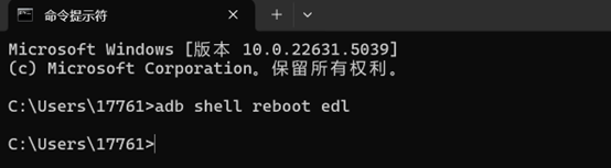
- Switch to flashing mode and execute "adb shell reboot edl".
9.2.2 Configure the Configuration item of QFIL
- Open QFIL, and click the Configuration-FireHose Configuration option at the top.

- In the pop-up Download Configuration window, make the following settings:
Select "0-Sahara" for Download Protocol.
Select "ufs" for Device Type.
Check the "Reset After Download" option.
All other options should be kept consistent with the following screenshot.
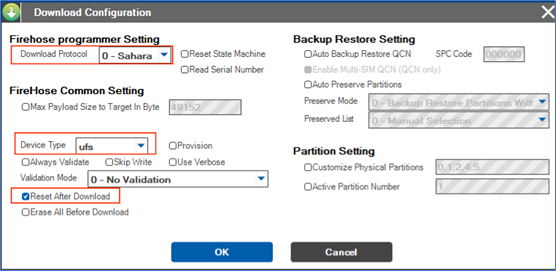
- After the configuration is completed, click OK to save.
9.2.3 Select the flashing port
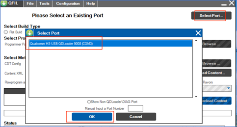
Click the "Select Port" option, in the pop-up window, select the displayed 9008 port, and click "OK".
After switching according to the section 9.2.1 Switch to flashing mode, the 9008 port option should automatically appear in this window. If it does not appear, please power off and restart the device, then perform the switch again and wait for it to appear.
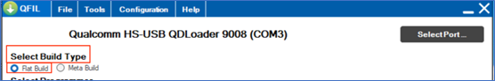
9.2.4 Select Build Type
- Find the "Select Build Type" item and select "Flat Build".
9.2.5 Select the flashing file
Unzip the ROM file
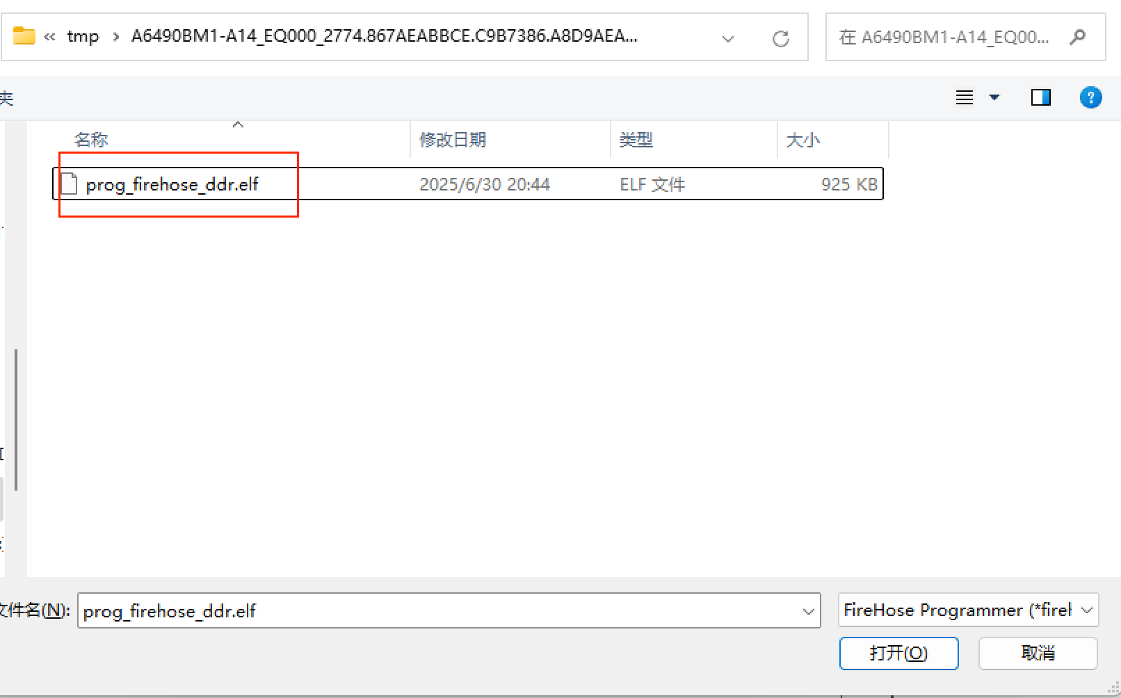
Find the "Select Programmer" item, click "Browse..." after "Programmer Path", locate the unzipped path, and select the unzipped ROM file.
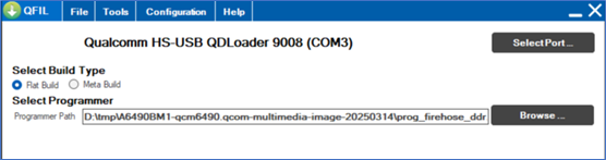
- Double-click to select "prog_firehose_ddr.elf".
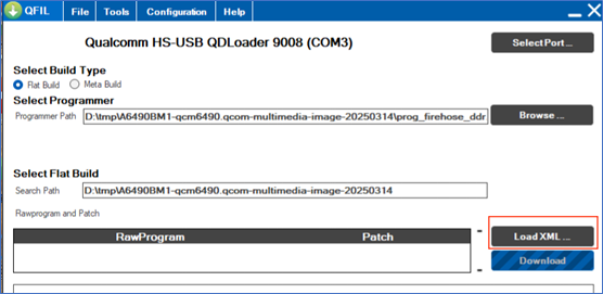
9.2.6 Full erase
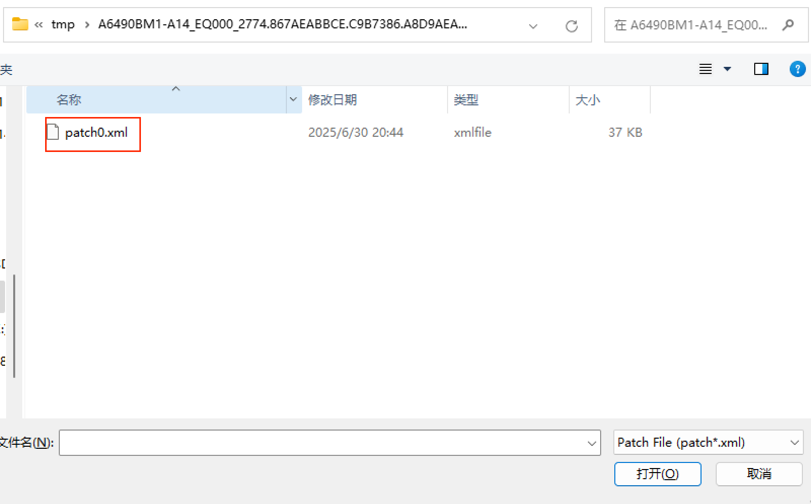
- Find the "Select Flat Build" item, click "Load XML..." below it, and select the full erase XML file.
- In the pop-up window, select the "rawprogram0_WIPE_PARTITIONS.xml" file.

- After selecting the XML file, another window will pop up automatically. Still select all the files.
- Click "Download" to start erasing.
9.2.7 Industrial mold
- After waiting for the erasure to complete, click "Load XML..." again and select the "rawprogram0_FFBM_split.xml" file.

- After selecting the XML file, another window will pop up automatically. Still select all the files.

- Click "Download" to start execution.
9.2.8 System firmware download
After flashing FFBM, the device will restart. At this point, wait for a while to see if ADB can be recognized. If ADB is recognized, execute "adb shell reboot edl" to enter the 9008 port download mode again.
After waiting for the execution to complete, click "Load XML..." again and select the "rawprogram0_split.xml" file.

- After selecting the XML file, another window will pop up automatically. Still select all the files.
- Click "Download" and wait for the flashing to complete.
10. AidLux System Installation
Tip
AidLux installation is only supported on integrated systems, which means an Android operating system needs to be installed.
10.1 Download of AidLux installation package
According to the selection you made when placing the order, Agix has pre-installed the corresponding AidLux version on the Rhino Pi A1 at the factory to help you quickly perform the unboxing operation experience (not the latest version). If you need to experience other versions, you can choose the version you need to download according to the following table.
| No. | AidLux Version | Version Download Path |
|---|---|---|
| 1 | AidLux-Ubuntu20.04 | aidlux_ubuntu20.04 |
| 2 | AidLux-Ubuntu22.04 | aidlux_ubuntu22.04 |
After the device is powered on, use a USB-Type-C cable to connect the computer and the device. Plug the USB port into the computer side, and the Type-C port into the device side. Once connected, execute: "adb devices".
adb devicesWhen the device is recognized, start the installation of the AidLux system.
Take the installation of the version "aidlux_2.0.1.1854_enterprise_qc6490_lu2204_robot_20250701-145237.zip" as an example.
10.2 New Installation Method 1
This method is suitable for installing the AidLux system on a Windows system.
- Obtain the system files, extract them locally. After extraction, there will be 4 files in the folder. Click install.bat to start the system installation.

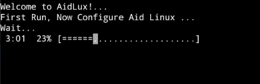
- When the interface prompts "Success", it indicates that the system has been installed successfully. Wait for the system to initialize.

- When the system initialization progress reaches 100%, the system installation is complete.
10.3 New Installation Method 2
This method is suitable for installing the AidLux system on non-Windows systems (Linux or macOS).
- Obtain the system files and extract them locally. After extraction, there will be 4 files in the folder. Upload the files to the /sdcard/Download directory of the device via the adb command.
Command:
adb push .\0.deb /sdcard/Download/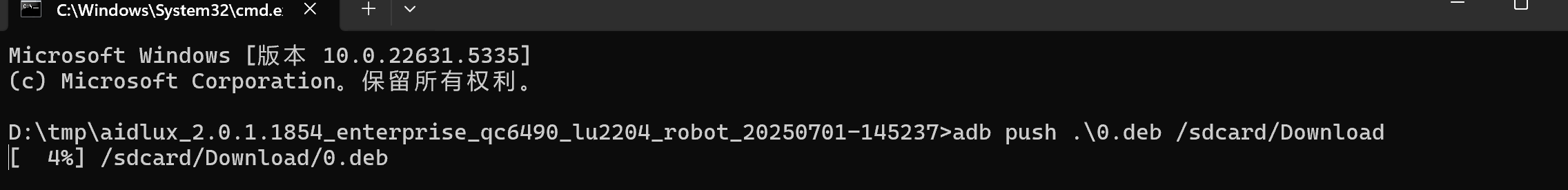
- After the 0.deb file is uploaded, execute adb install to install the apk.
Command:
adb install .\aidlux_2.0.1.1854_enterprise_qc6490_lu2204_robot_20250701-145237.apk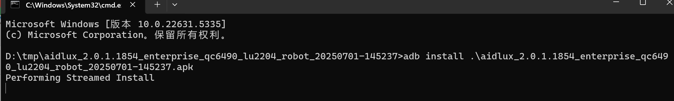
If "Success" is prompted, it indicates that the installation is successful.
Enter the Android system, click the AidLux icon, and perform system initialization.
![]()
- When the system initialization progress reaches 100%, the system installation is complete.
Tip
The system has a default trial period of 1 month. For system authorization, please contact the sales staff of Agix.
11.Robot Peripheral Kit Test
At present, the Rhino Pi A1 has passed internal tests for the following robot peripheral kits. However, the actual supported kits are not limited to those listed in the table below, and there are more kits waiting for you to explore.
| NO. | Device Type | Device Name |
|---|---|---|
| 1 | USB to Serial Port Device | USB TO 4CH TTL USB TO 8CH TTL CH9102 CP2102 |
| 2 | Depth Camera | Intel RealSense D415 |
| 3 | LiDAR | Laser LDS-50C-E |
| 4 | Audio Kit | AISPEECH bothlent Power Amplifier Board HSY 1.5-inch Full-range Speaker with Sound Cavity |
| 5 | Ultrasonic Sensor | DYP-A02YY-V2.0 (without shell) |
| 9 | TOF Sensor | Nooploop TOFSense Series |
| 10 | Temperature and Humidity Sensor | SM7820B |
11.1 USB TO 4CH TTL
- Official documentation of the kit: USB TO 4CH TTL
11.1.1 Preparation
- Rhino Pi A1
- USB TO 4CH TTL serial port device
- CH340 USB TO TTL test board
- Several Dupont wires
- Windows computer
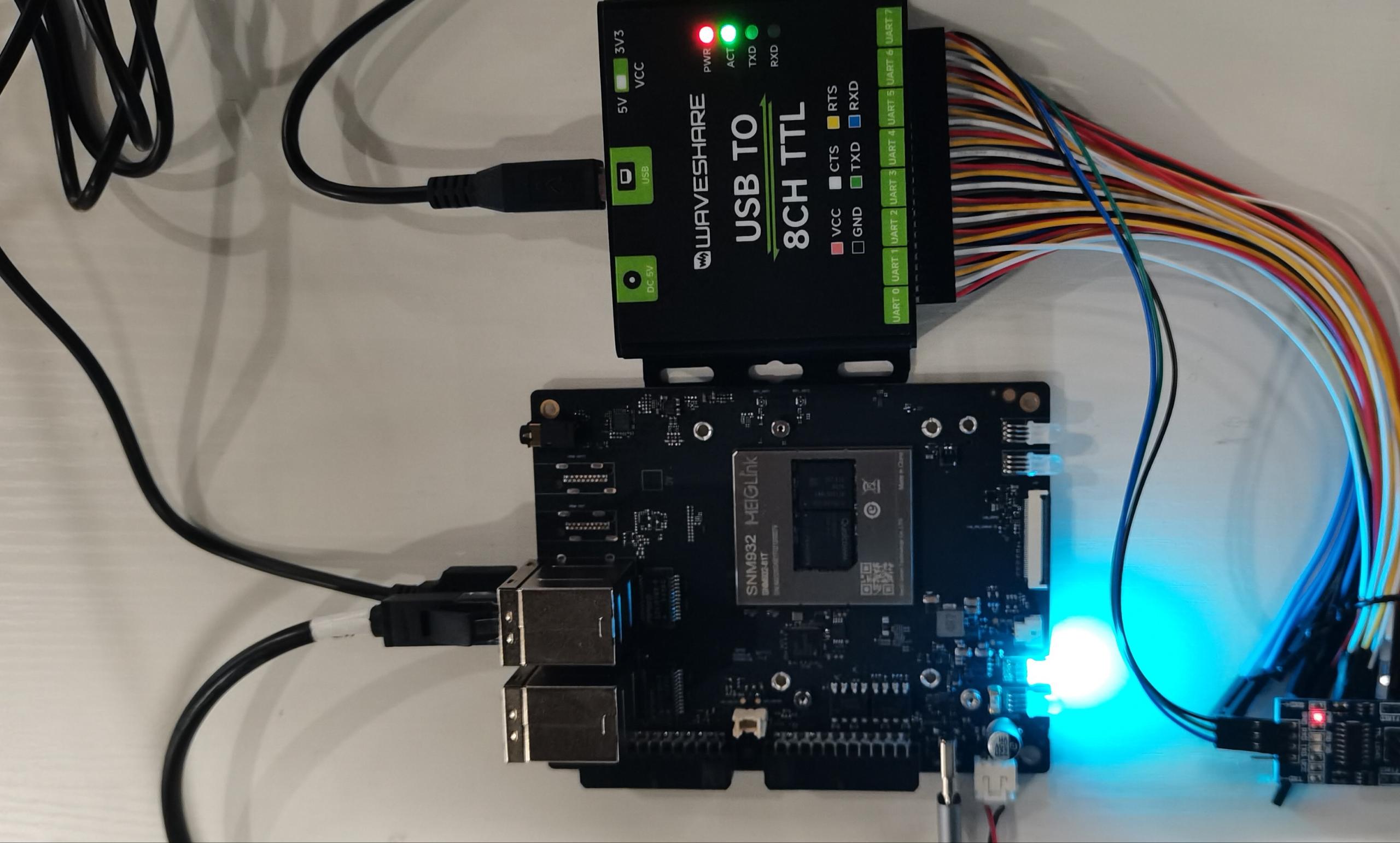
11.1.2 Hardware Connection
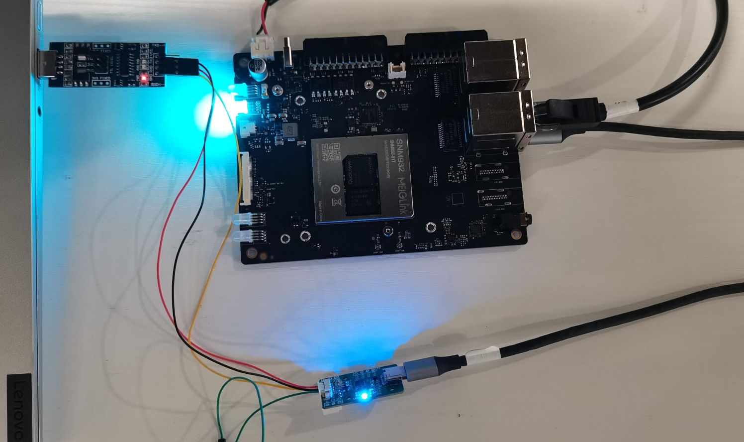
- The development board is connected to the CH344 device via a USB interface.
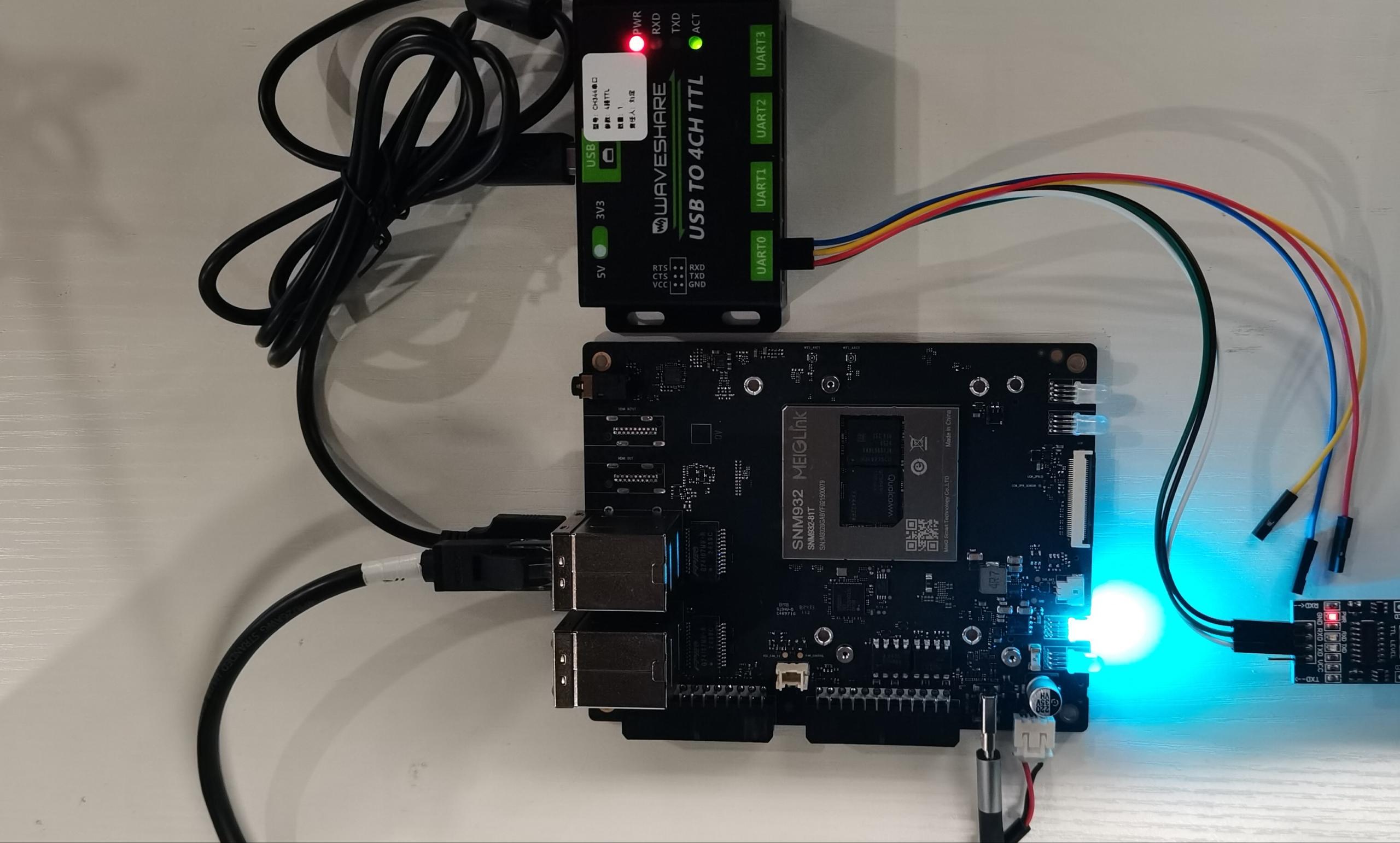
- The CH340 test board connects the USB port of a Windows computer and the CH344 device.
Among them: The RXD, TXD, and GND of CH344 are connected to the TXD, RXD, and GND of CH340 respectively.

11.1.3 Testing
💡Note
When executing commands in the terminal on the AidLux desktop, if you need to enter the aidlux password, please input: aidlux
After obtaining the IP address of the Agix development board, log in to the AidLux Web desktop through a browser. For specific login methods, please refer to the hardware guide Login Chapter.
After logging in, enter the following command in the AidLux terminal to check whether the CH344 serial port device has been recognized.
ls -l /dev/ttyC*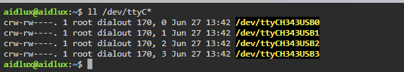
💡Note
The device names of the CH344 multi-channel serial port correspond one-to-one with the actual physical UART interface names, that is: /dev/ttyCH343USB0 corresponds to device UART0; /dev/ttyCH343USB1 corresponds to device UART1. 以此类推。
- Use the stty tool in the AidLux terminal to configure the device's UART port.
stty -F /dev/ttyCH343USB0 115200   # Set the baud rate of ttyCH343USB0 to 115200.
stty -F /dev/ttyCH343USB0 -isig -icanon iexten -echo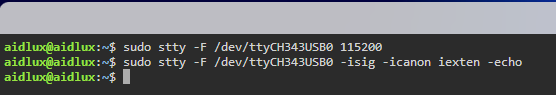
- Open the "Serial Port Debugging Tool" on the Windows computer, and open the corresponding serial port and set the baud rate (keep it consistent with the setting in the AidLux terminal).

After setting up both the "Serial Port Debugging Tool" on the Windows computer side and the terminal on the AidLux side, you can perform the test of sending and receiving information.
AidLux side information reception test
Execute the command in the AidLux terminal to check the received messages.
sudo cat /dev/ttyCH343USB0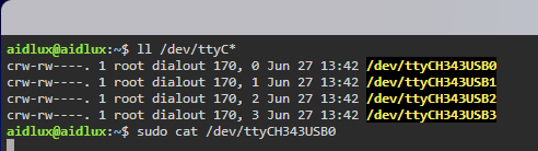
Send a message using the "Serial Port Debugging Tool" on the Windows computer, and at the same time, you can check whether the message can be received on AidLux.

- AidLux side information sending test:
Execute commands on the AidLux terminal to send information, and at the same time, you can check whether the information can be received on the "Serial Port Debugging Tool".
echo 123abc > /dev/ttyCH343USB0💡Note
If you are prompted that you have no permission, please execute the command: "sudo su" to switch to the root user before testing. You need to enter the password: aidlux

11.2 USB TO 8CH TTL
- Official Documentation of the Suite: USB TO 4CH TTL
11.2.1 Preparation
- Rhino Pi A1
- USB TO 8CH TTL serial port device
- CH340 USB TO TTL test board
- Several Dupont wires
- Windows computer
11.2.2 Hardware Connection
- The development board is connected to the CH348 device via a USB interface, and the CH340 test board is connected to the USB port of the Windows computer and the CH348 device.
Among them: The RXD, TXD, and GND of CH348 are connected to the TXD, RXD, and GND of CH340 respectively.
11.2.3 Test
💡Note
When executing commands in the terminal on the AidLux desktop, if you need to enter the Aidlux password, please input: aidlux
After obtaining the IP address of the Agix development board, log in to the AidLux Web desktop through a browser. For the specific login method, please refer to the Login Chapter in the hardware guide.
After logging in, enter the following command in the AidLux terminal to check whether the CH348 serial port device has been recognized.
ls -l /dev/ttyC*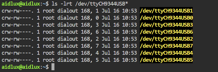
💡Note
The device names of the CH348 multi-channel serial port correspond one-to-one with the actual physical UART interface names, that is: /dev/ttyCH9344USB0 corresponds to device UART0; /dev/ttyCH9344USB1 corresponds to device UART1, and so on.
- Install the minicom tool
minicom is not installed by default in AidLux, and it can be installed using the following command:
sudo apt update
sudo apt install minicom- The Rhino Pi A1 uses the minicom tool to open the serial port device.
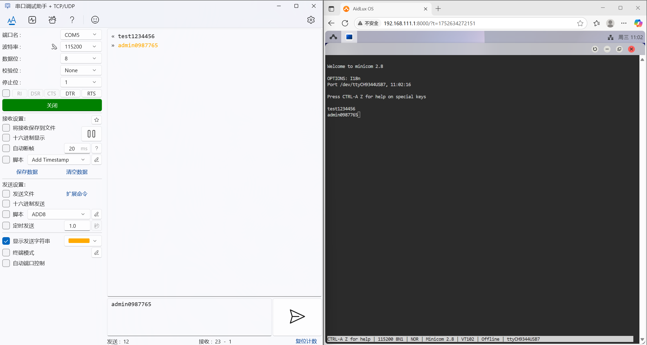
If the currently connected UART7 port of CH348 is used, execute the following command to open the serial port device:
sudo minicom -D /dev/ttyCH9344USB7 -b 115200- On the Windows side, use a serial port debugging tool to open the serial port device.
A serial port debugging tool can be installed on Windows. After opening the tool, select the corresponding port and open it. Note: The baud rate must be consistent with that set when the minicom tool on the Rhino Pi A1 opens the port, such as 115200.
- Test sending messages to each other between the two ends
You can enter any characters in minicom for sending tests, and the serial port debugging tool on Windows will be able to see the received information; vice versa.
Tip
By default, minicom does not print input characters. You can press Ctrl-A Z E keys in sequence to set it to display input information.
11.3 CH9102
11.3.1 Preparation
- Rhino Pi A1
- CH9102 serial port device
- CH340 USB TO TTL test board
- Several Dupont wires
- Windows computer
11.3.2 Hardware Connection
- The development board is connected to the CH9102 device via a USB interface, and the CH340 test board is connected to the USB port of the Windows computer and the CH9102 device.
Among them: The RXD, TXD, and GND of CH9102 are connected to the TXD, RXD, and GND of CH340 respectively.
11.3.3 Test
💡Note
When executing commands in the terminal on the AidLux desktop, if you need to enter the aidlux password, please input: aidlux
After obtaining the IP address of the Agix development board, log in to the AidLux Web desktop via a browser. For the specific login method, please refer to the Login Chapter in the hardware guide.
After logging in, enter the following command in the AidLux terminal to check whether the CH9102 serial port device has been recognized.
ls -l /dev/ttyC*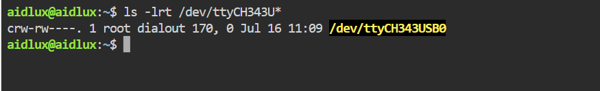
- Configure the serial port device number using the stty tool
chmod 777 /dev/ttyCH343USB0                              //Grant permissions to the serial port device number
stty -F /dev/ttyCH343USB0 115200                         //Set the baud rate of the serial port device number
stty -F /dev/ttyCH343USB0 -isig -icanon iexten -echo //Set others- On the Windows side, use a serial port debugging tool to open the serial port device.
A serial port debugging tool can be installed on Windows. After opening the tool, select the corresponding port and open it. Note: The baud rate must be consistent with that set by the stty tool on the Rhino Pi A1, such as 115200.
- Test of sending messages to each other between the two ends
Characters can be sent to the serial port device number through the echo command, and it can be observed that the serial port tool on the Windows side receives the information; conversely, when the serial port tool on the Windows side sends characters, the information can be received through the cat command on the Rhino Pi A1 side.
Sending command:
echo 'demo123' > /dev/ttyCH343USB0Receiving command:
cat /dev/ttyCH343USB0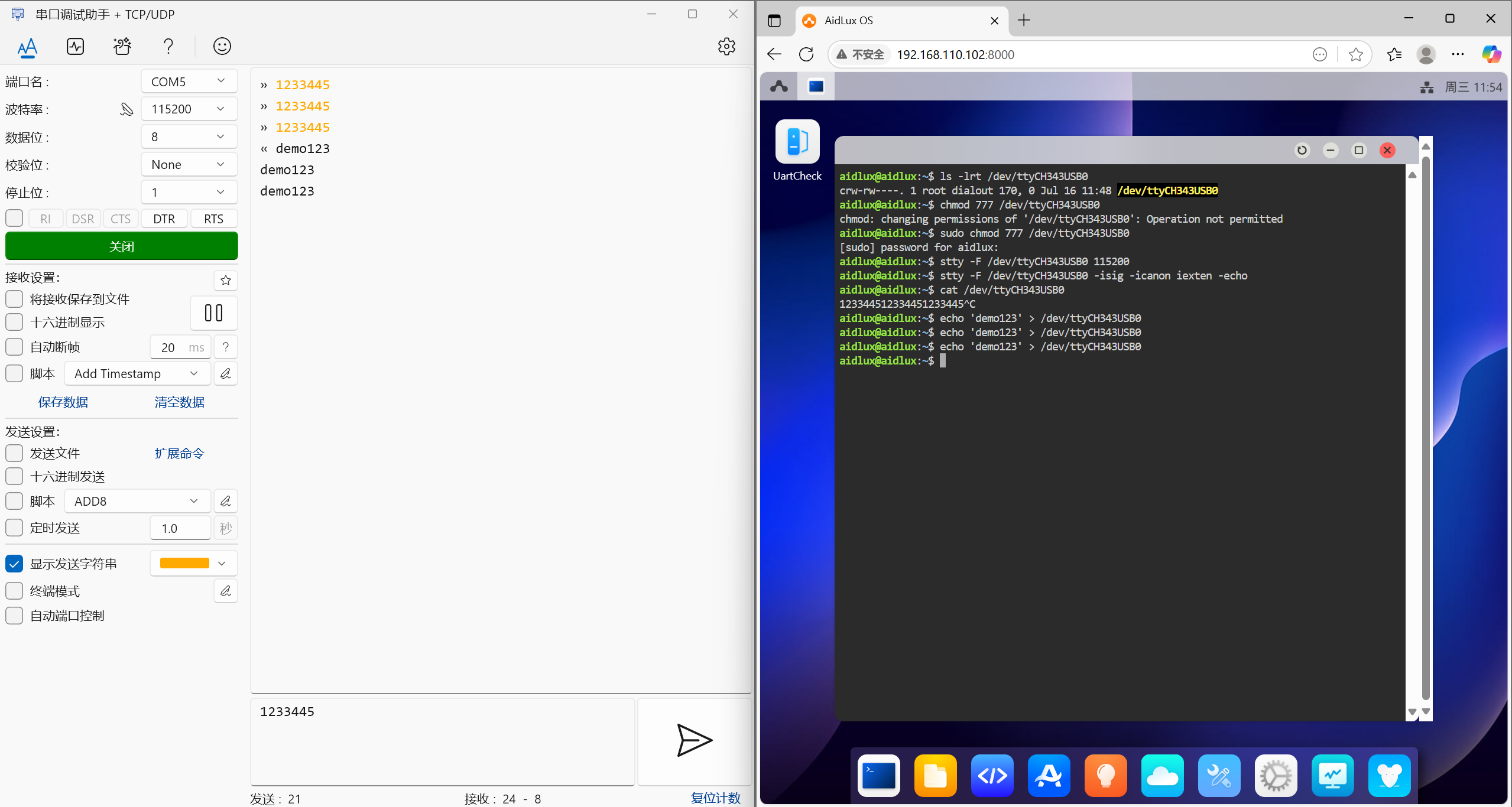
11.4 CP2102
- Official documentation of the kit: CP2102
11.4.1 Preparation
- Rhino Pi A1
- CP2102 serial port device
- CH340 USB TO TTL test board
- Several Dupont wires
- Windows computer
11.4.2 Hardware Connection
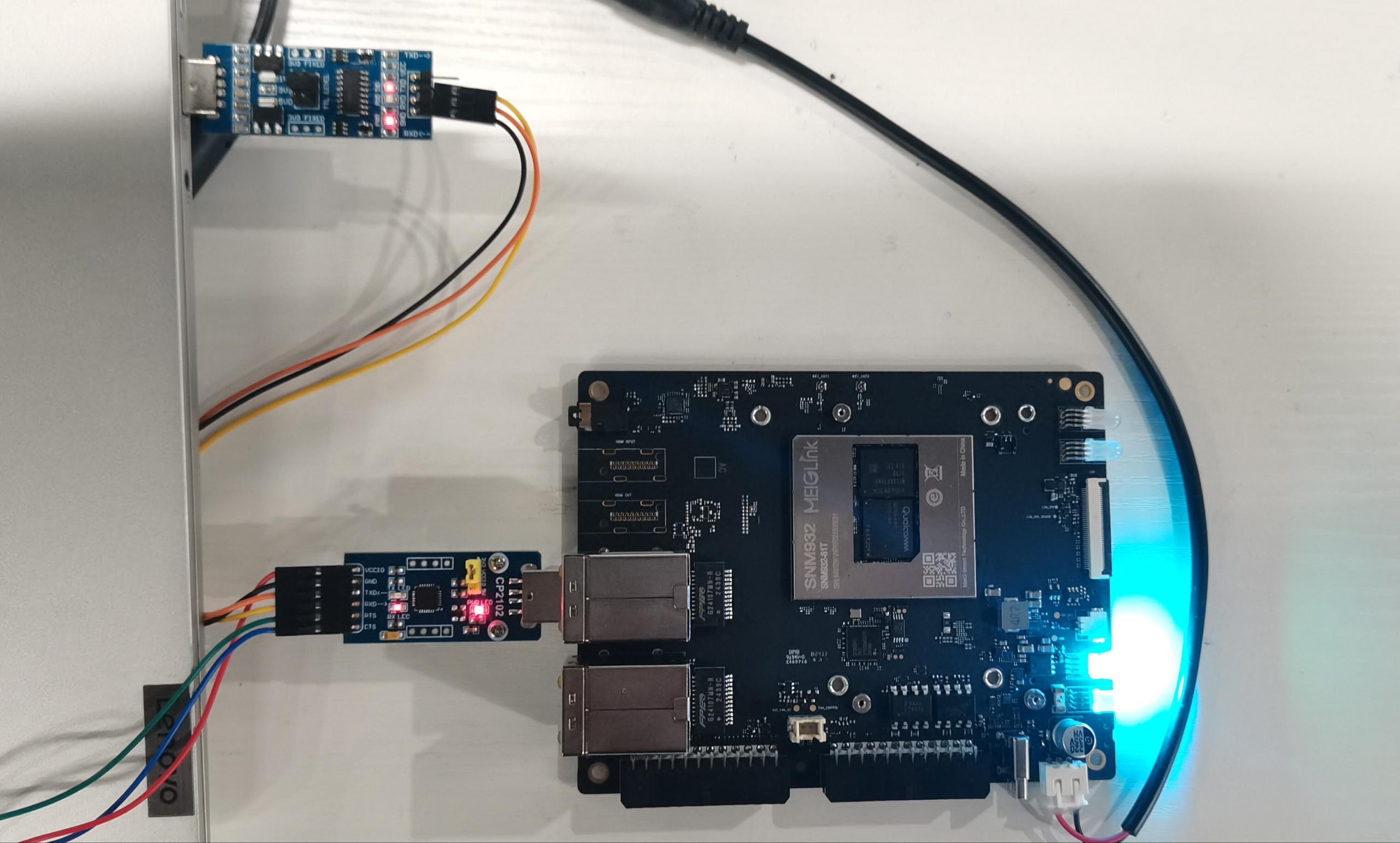
- The development board is connected to the CP2102 device via a USB interface, and the CH340 test board is connected to the USB port of the Windows computer and the CP2102 device.
Among them: The RXD, TXD, and GND of CP2102 are connected to the TXD, RXD, and GND of CH340 respectively.
11.4.3 Test
💡Note
When executing commands in the terminal on the AidLux desktop, if you need to enter the aidlux password, please input: aidlux
After obtaining the IP address of the Agix development board, log in to the AidLux Web desktop via a browser. For the specific login method, please refer to the Login Chapter in the hardware guide.
After logging in, enter the following command in the AidLux terminal to check whether the CP2102 serial port device has been recognized.
ls -l /dev/ttyU*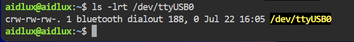
- Configure the serial port device number using the stty tool
chmod 777 /dev/ttyUSB0                              //Grant permissions to the serial port device number
stty -F /dev/ttyUSB0 115200                         //Set the baud rate of the serial port device number
stty -F /dev/ttyUSB0 -isig -icanon iexten -echo //Set others- Use a serial port debugging tool on the Windows side to open the serial port device.
A serial port debugging tool can be installed on Windows. After opening the tool, select the corresponding port and open it. Note: The baud rate must be consistent with that set by the stty tool on the Rhino Pi A1, such as 115200.
- Test of sending messages to each other between the two ends
Characters can be sent to the serial port device number via the echo command, and it can be observed that the serial port tool on the Windows side receives the information; conversely, when characters are sent through the serial port tool on the Windows side, the information can be received via the cat command on the Rhino Pi A1 side.
Sending command:
echo 'demo111' > /dev/ttyUSB0Receiving command:
cat /dev/ttyUSB0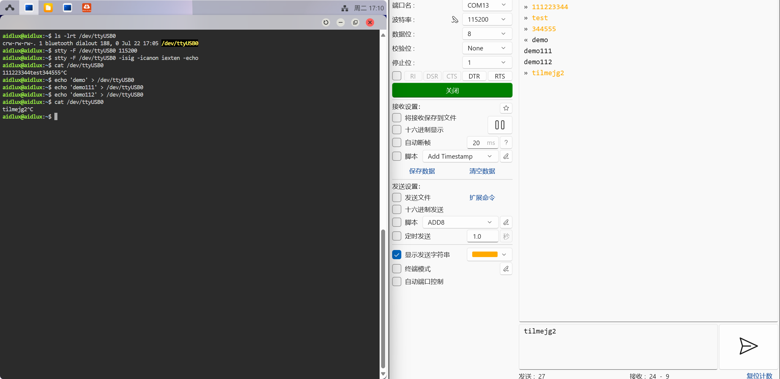
11.5 Intel RealSense D415
11.5.1 Preparation
Rhino Pi A1
Ubuntu Desktop, ROS 2, and RViz 2 are preinstalled on AidLux-Ubuntu 22.04. For specific installation methods, please refer to the Robot Software Installation Guide
Intel RealSense D415 Depth Camera and Installation of Its Driver
The installation method is as follows:
After installing Ubuntu Desktop and connecting via a VNC tool, you can execute the following commands in the terminal window:
sudo apt-get update
sudo apt-get install ros-humble-realsense2-camera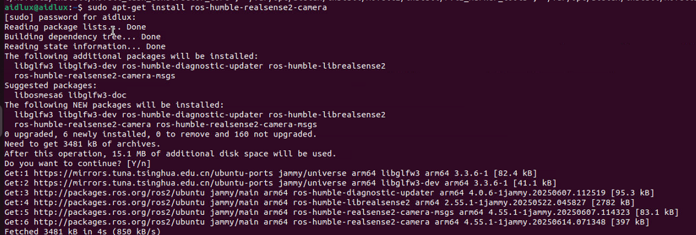
11.5.2 Hardware Connection
Connect the depth camera to the USB port of the Rhino Pi.
11.5.3 Test
- After the connection is established, start the camera driver using the following command.
ros2 launch realsense2_camera rs_launch.py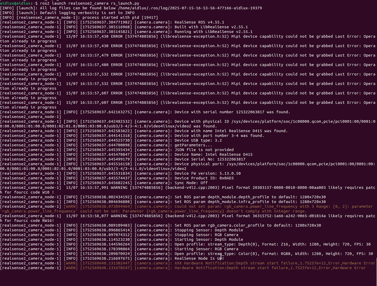
- Open RViz 2
Open the terminal and enter: rviz2
rviz2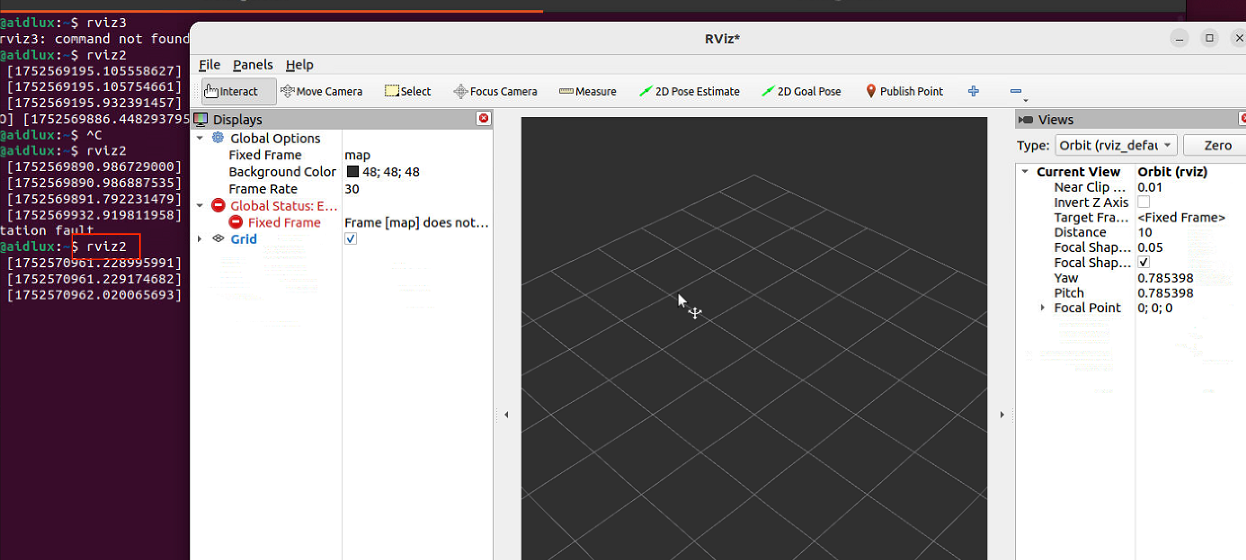
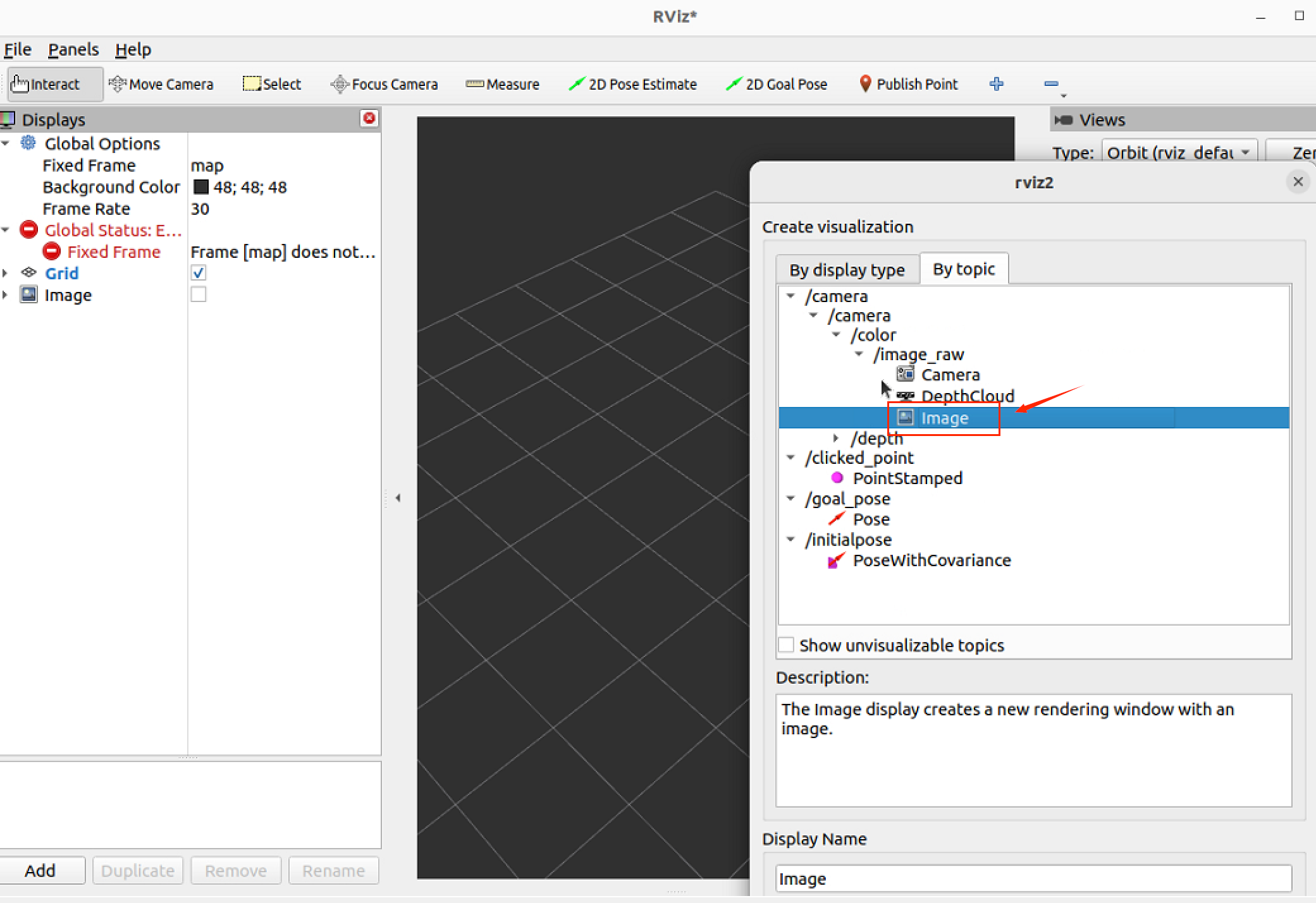
- Verify that the depth camera image is displayed in RViz 2
Click the Add button in the bottom-left corner
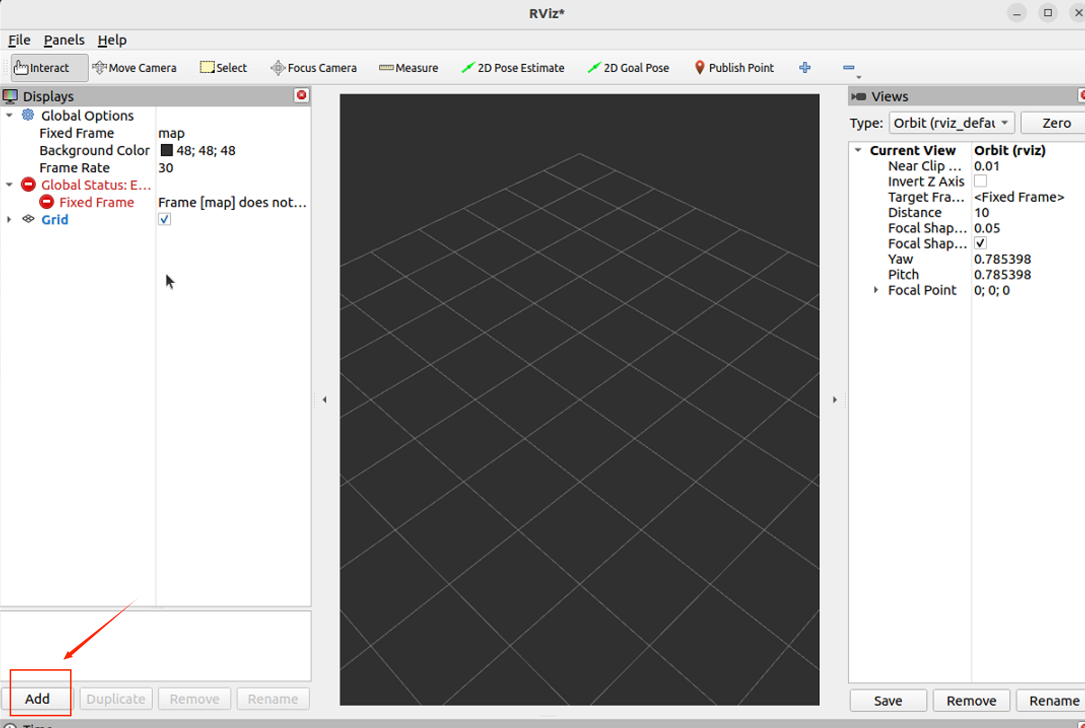
Click By topic in the pop-up window
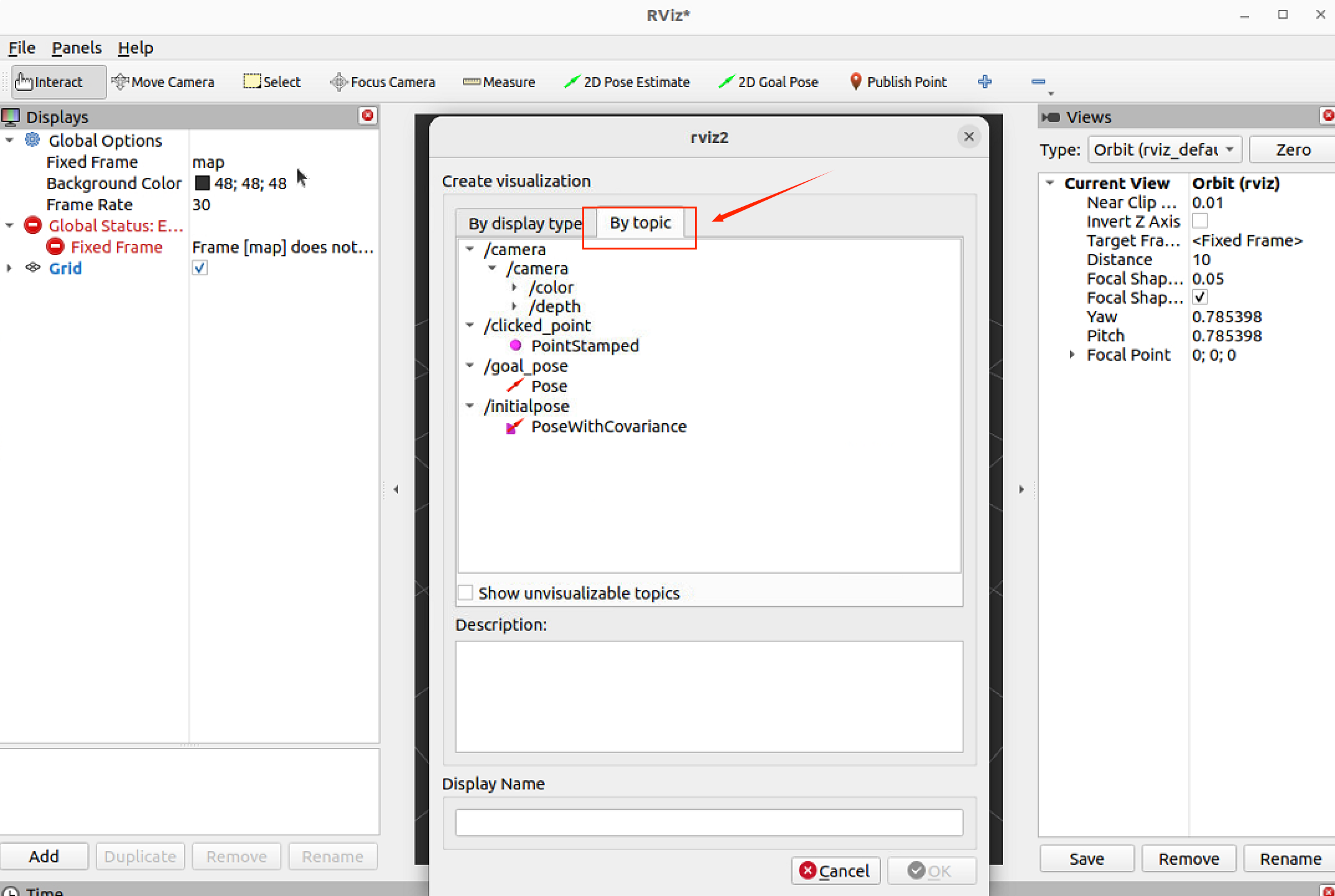
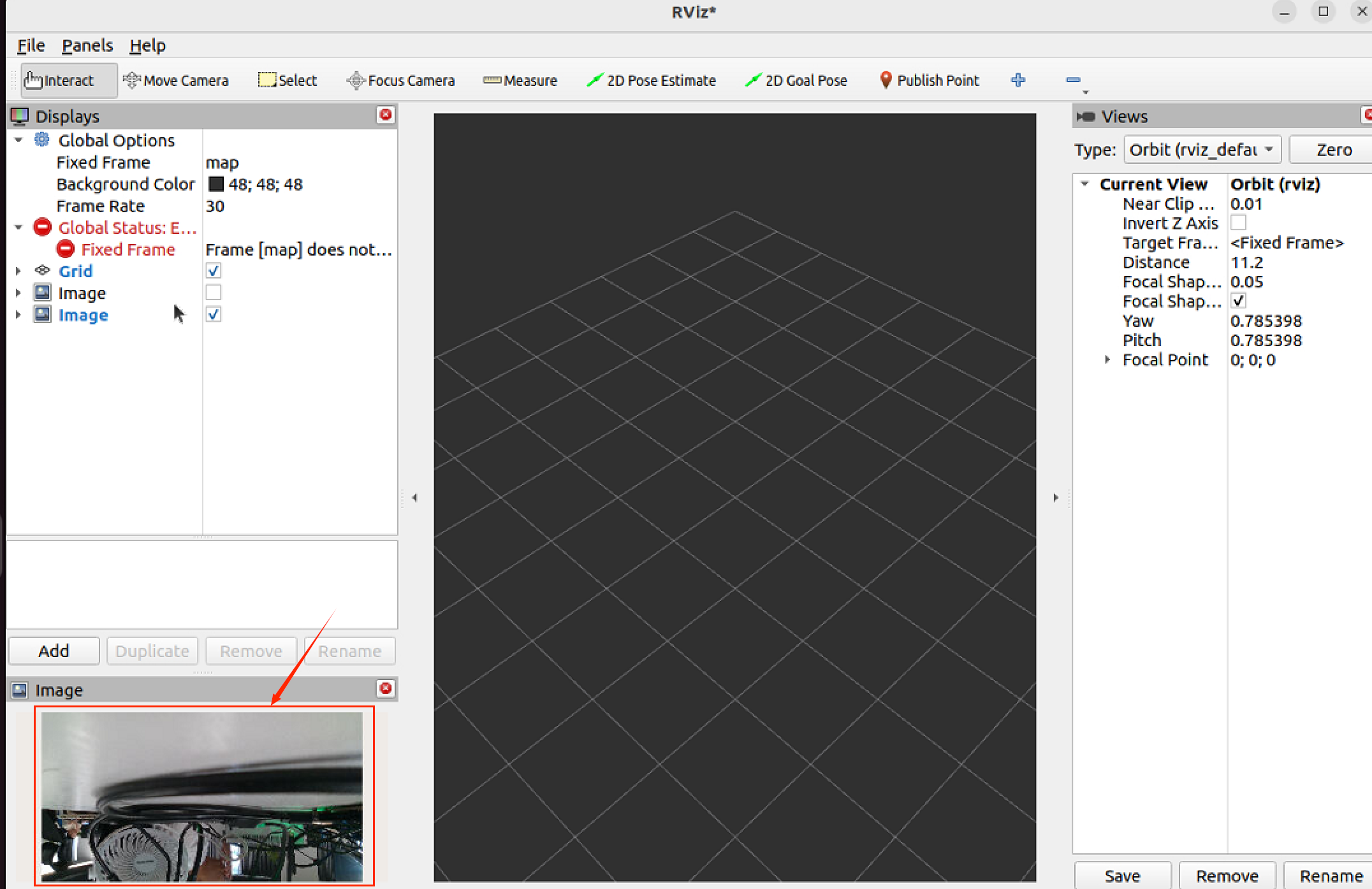
Double-click to open the "image" under the "/camera" node, and observe that the "image" pop-up window in the bottom-left corner displays the 画面 captured by the camera.
11.6 Laser LDS-50C-E Lanhai LiDAR
11.6.1 Preparation
- Rhino Pi A1
- Preinstall Ubuntu Desktop, ROS 2, and RViz 2 on AidLux-Ubuntu 22.04
The specific installation method can refer to Robot Software Installation Guide
- Laser LDS-50C-E (Lanhai Laser Radar)
- 12V Power Supply for the Radar
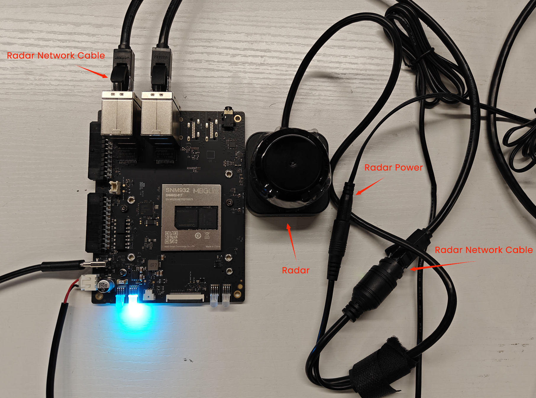
11.6.2 Hardware Connection and Network Configuration
Connect the radar to a 12V power supply, connect the Ethernet port to any Ethernet port of the Rhino Pi A1, and configure the default IP (you can use the ifconfig command to configure a temporary IP).
A standard Ethernet cable is used to connect the LDS-50C-E and the Rhino Pi A1 via their standard Ethernet interfaces. To ensure normal communication between the radar and the Rhino Pi A1, they need to be on the same network segment. The factory settings of the radar are as follows:
Radar IP: 192.168.158.98
Radar Subnet Mask: 255.255.255.0
Radar Gateway: 192.168.158.1
Radar Default Upload Address: 192.168.158.15
The network settings of Rhino Pi are as follows:
Ethernet Port IP: 192.168.158.15
Ethernet Port Subnet Mask: 255.255.255.0
Ethernet Port Gateway: 192.168.158.1
After connecting the Ethernet cable and configuring the IP address, check if the network is connected using the Ping command.
11.6.3 Obtain and build the Lanhai ROS 2 Driver Package
After opening the Ubuntu desktop via a VNC tool, execute the following commands in sequence:
- Obtain the Lanhai ROS 2 driver from GitHub and deploy it to the corresponding location
sudo su  //密码: aidlux

mkdir bluesea2
cd bluesea2
git clone https://github.com/BlueSeaLidar/bluesea-ros2.git src- Install Dependencies
sudo apt update
sudo apt install -y python3-colcon-common-extensions- Build
colcon build- Update the current ROS 2 package environment
source ./install/setup.sh- Run the driver using ROS 2 launch
ros2 launch bluesea2 udp_lidar.launch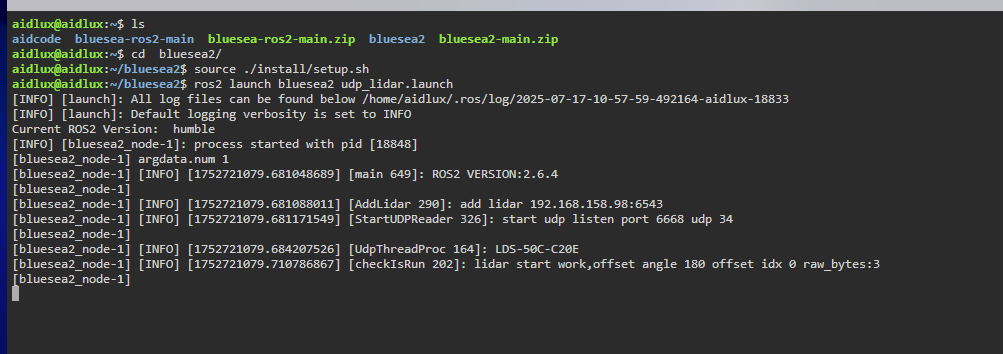
11.6.4 Test
After opening the Ubuntu desktop via a VNC tool, execute the following commands in sequence:
- Data Verification: Scan to check if the output is normal
ros2 topic echo /scan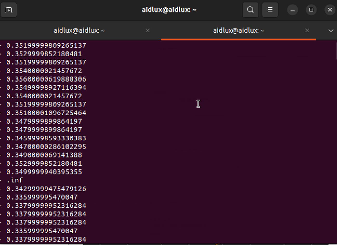
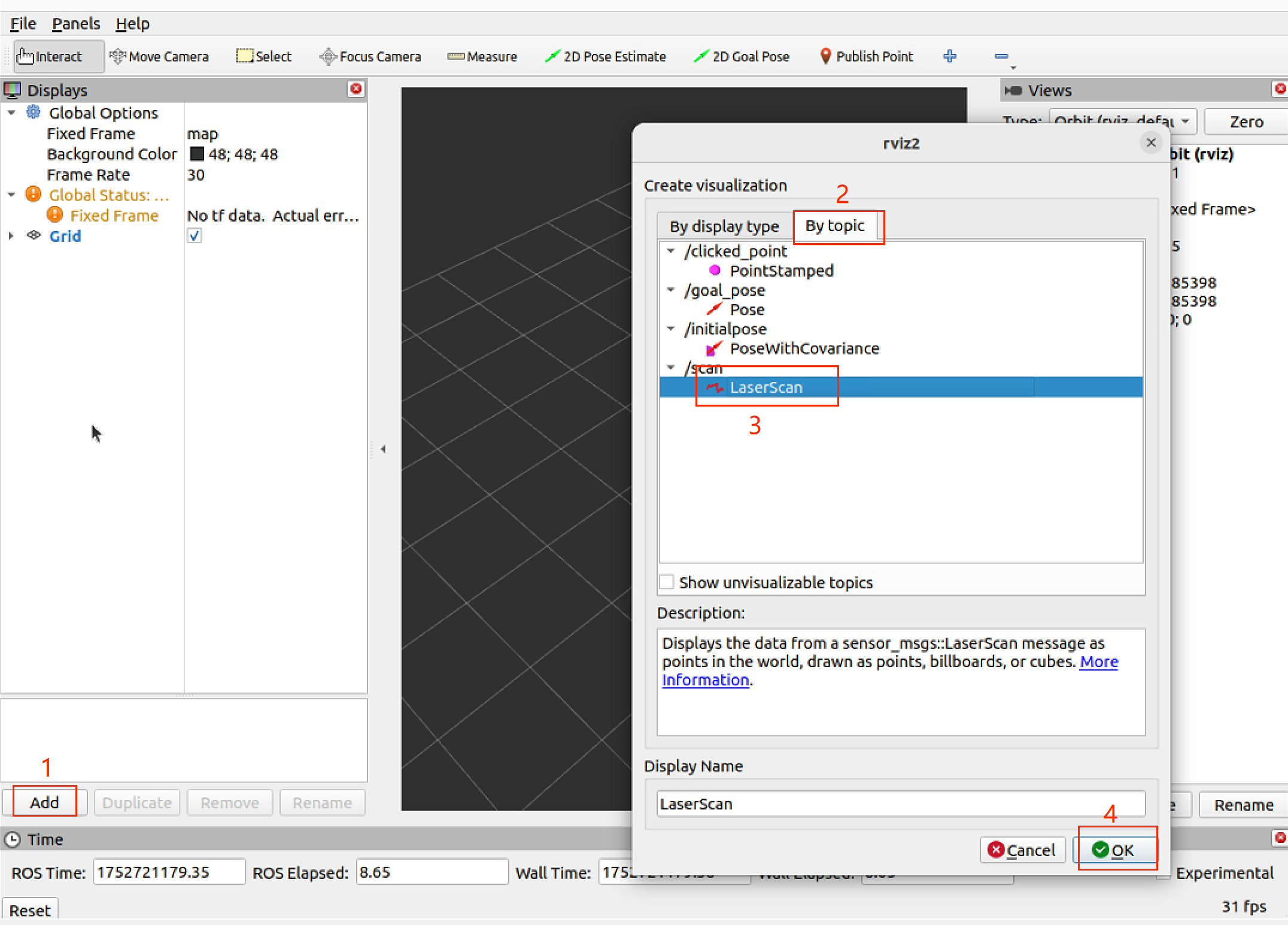
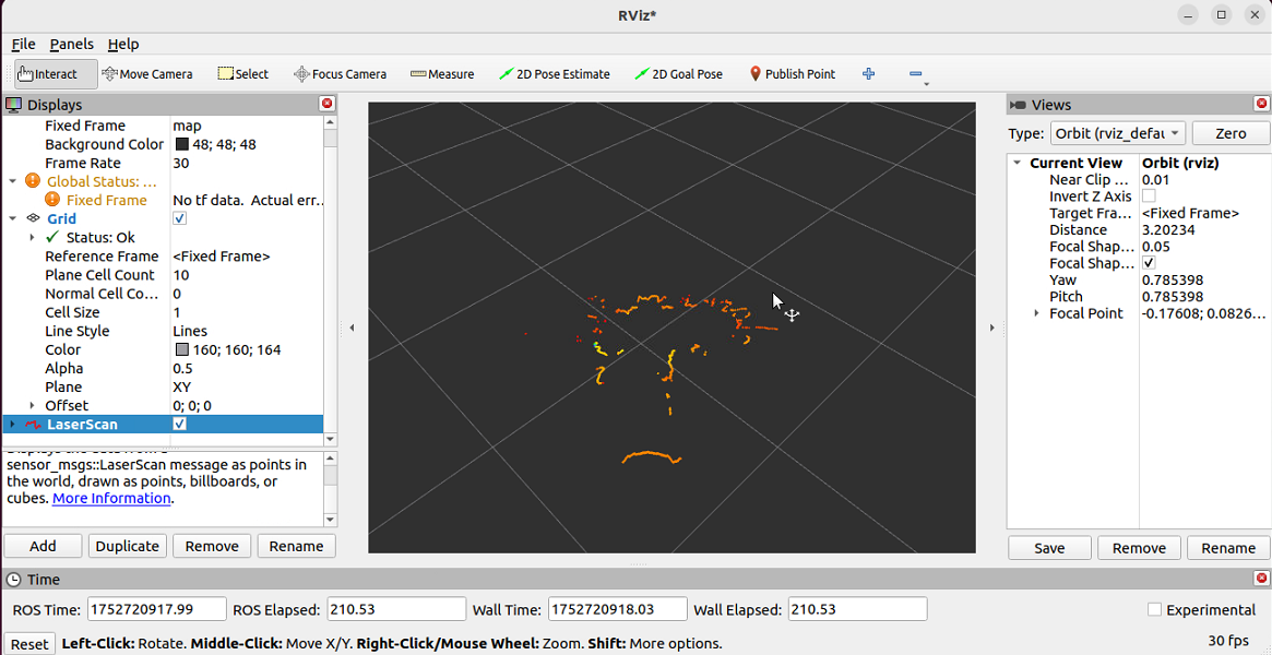
- Open the visualization tool RViz2
rviz2- After opening it, click the following buttons in sequence to open the visualization interface LDS50C-keshihua.png
11.7 Audio Kit
The audio kit recommended by APLUX includes three parts: HSY full-range speaker, Yuliang power amplifier board, and SBC microphone. The following will introduce how to connect these three parts.
11.7.1 Preparation
- Rhino Pi A1
- HSY 1.5-inch full-range speaker with sound cavity
- Yuliang power amplifier board
- SBC microphone
- Several other connecting cables
11.7.2 Hardware Connection
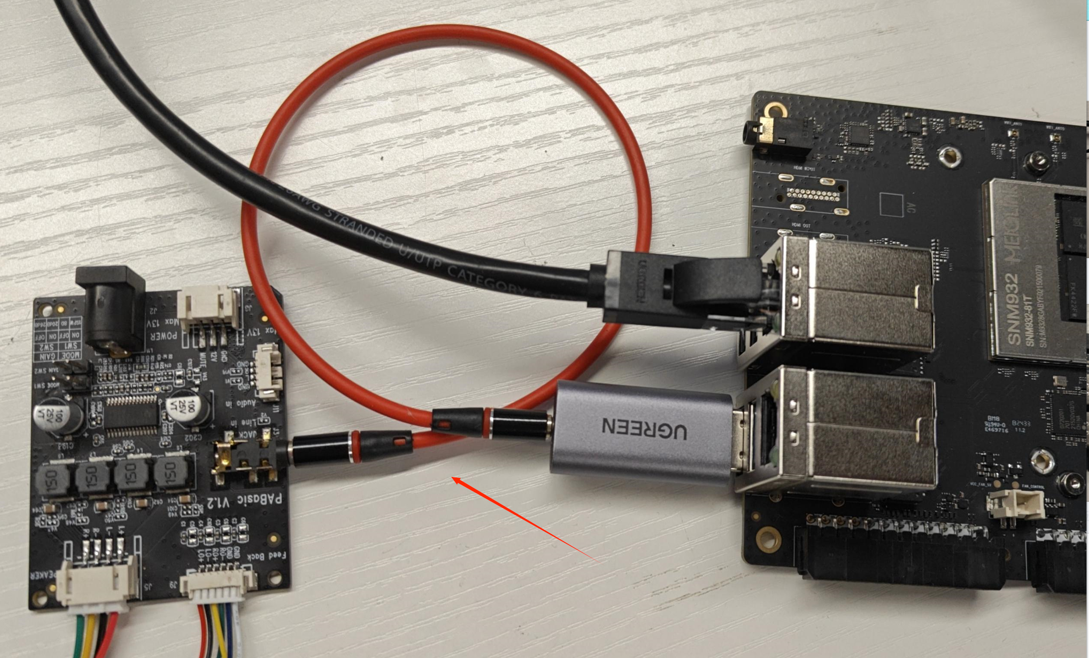
Overall Connection Diagram:
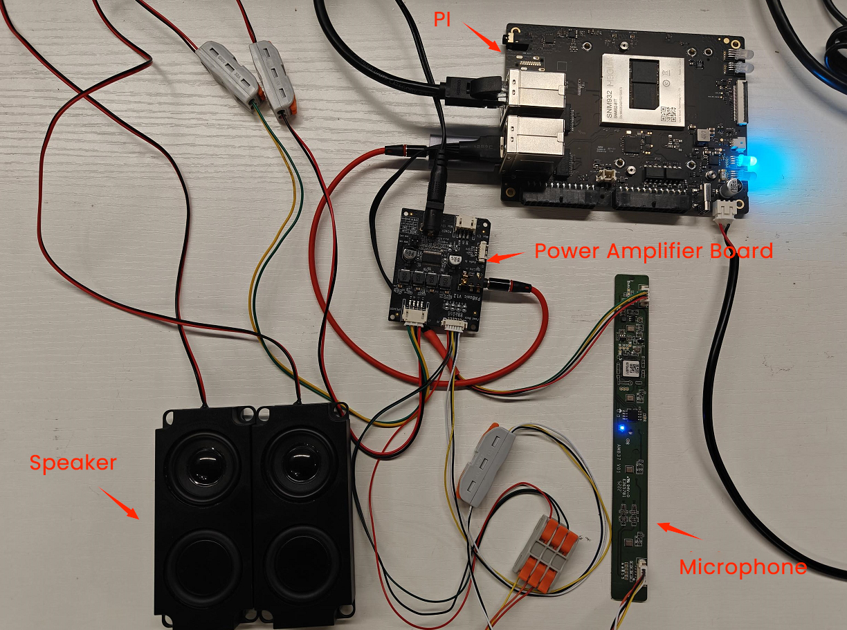
HSY Speaker Connected to Yuliang Power Amplifier Board
For the HSY Speaker: the red cable is positive, and the black cable is negative. Connect them to the "L+" or "R+" (for positive) and "L-" or "R-" (for negative) terminals on the power amplifier board respectively. If there are two speakers, they need to be connected to the left and right channels of the power amplifier board separately (i.e., one speaker to "L+" and "L-", and the other to "R+" and "R-"). 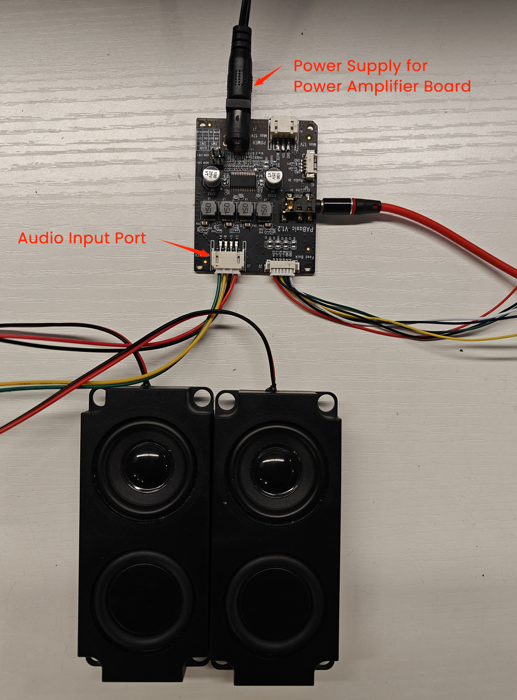
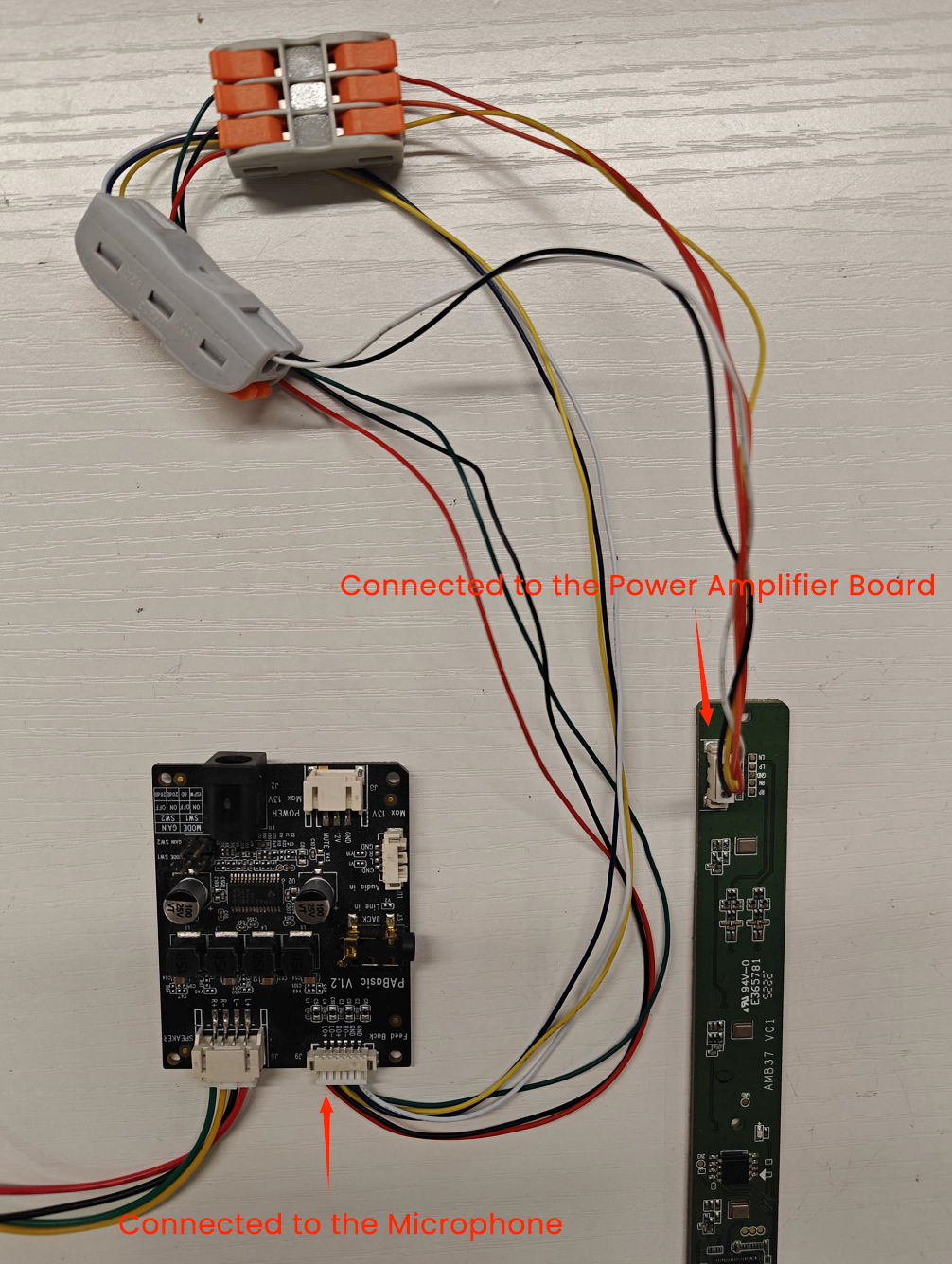
- One side of the SBC microphone is connected to the Yuliang power amplifier board.
The LP, LN, GND, RP, and RN terminals of the microphone are connected to the LO+, LO-, GND, RO+, and RO- terminals of the power amplifier board respectively. Note: There are two GND terminals on the power amplifier board, and both need to be connected to the GND terminal of the microphone.
LP - LO+
LN - LO-
GND - GND
RP - RO+
RN - RO-
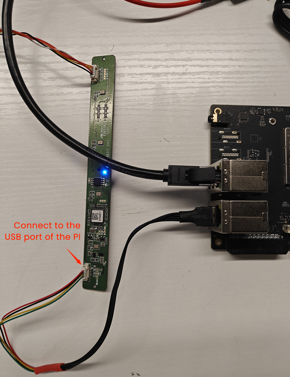
- The other side of the SBC microphone is connected to the USB port of the Rhino Pi A1.
A DIY cable is required. Wire sequence: Connect the 5V, DP, DM, and GND (of the microphone) to the 5V (red), Data+ (green), Data- (white), and GND (black) of the stripped USB cable respectively.
- The power amplifier board is connected to the USB port of the Rhino Pi A1
The 3.5mm audio interface of the power amplifier board is connected to the USB-to-3.5mm interface converter, and then plugged into the USB port of the Rhino Pi A1.
11.7.3 Test
11.7.3.1 Recording Test
- List All Recording Devices
sudo arecord -l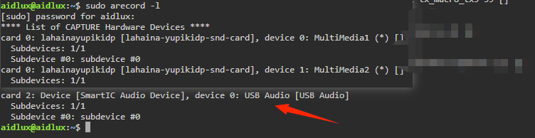
Find "USB Audio", then read the sound card number of this device (denoted as "card x", where x is the sound card number) and the device number under this sound card (denoted as "device y", where y is the sub-device number). The device identifier format is: hw:X,Y (X stands for the sound card number, and Y stands for the sub-device number). The device identifier read in the current example is: hw:2,0
- List the various parameters supported by the device
sudo arecord -D hw:2,0 --dump-hw-params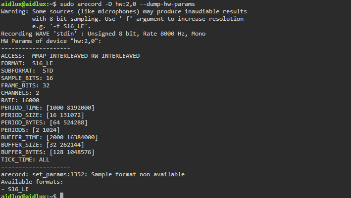
Note the following parameters:
FORMAT: The sample format supported by the device. The currently supported format is: S16_LE
CHANNELS: Indicates the range of the number of channels supported by the device. The current number of channels is: 2
RATE: Displays the range of sample rates supported by the device, with the unit being Hz. The currently supported sample rate is: 16000
- Start Recording
Note that the parameters in the command need to be consistent with the values retrieved in the previous step. For example, -f refers to the sample format, -r refers to the sample rate, -c refers to the number of channels, and -d refers to the recording duration.
sudo arecord -D hw:2,0 -f S16_LE -r 16000 -c 2 -d 5 output.wav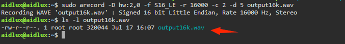
11.7.3.2 Playback Test
- List All Playback Devices
sudo aplay -l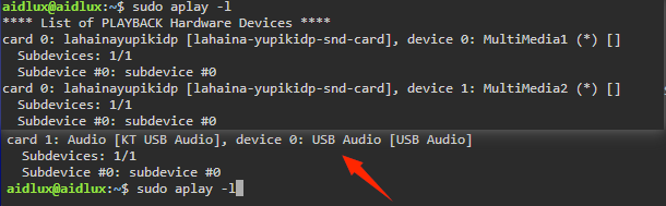
Find "USB Audio", then read the sound card number of this playback device (denoted as "card x", where x is the sound card number) and the device number under this sound card (denoted as "device y", where y is the sub-device number). The device identifier format is: hw:X,Y (X is the sound card number, and Y is the sub-device number). The device identifier read in the current example is: hw:2,0
- List the various parameters supported by the device
sudo aplay -D hw:1,0 --dump-hw-params /dev/zero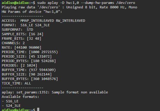
Note the following parameters:
FORMAT: The sample formats supported by the device. The currently supported formats are: S16_LE, S24_3LE
RATE: Displays the range of sample rates supported by the device, with the unit being Hz. The currently supported sample rates are: 44100, 96000
From the above parameter values, it can be seen that the sample rate of the playback device is inconsistent with that of the recording device. The sample rate of the recording device is 16000, while that of the playback device is 44100 and 96000. Therefore, we need to convert the sample rate of the recorded audio (e.g., convert it to a sample rate of 44100). The method is as follows:
Install the Conversion Tool
sudo apt update
sudo apt install sox libsox-fmt-all
Start Conversion
sudo sox output16k.wav -r 44100 output44k.wav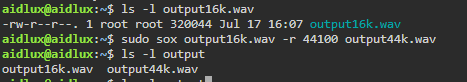
- Start playing the recorded audio
Note that the parameters in the command must be consistent with the values retrieved in the previous step. For example, -f refers to the sample format, -r refers to the sample rate, and -c refers to the number of channels.
sudo aplay -D hw:1,0 -f S16_LE -r 44100 -c 2 output44k.wav
11.8 DYP-A02YY-V2.0 Ultrasonic Sensor
11.8.1 Preparation
- Rhino Pi A1
- DYP-A02YY-V2.0 Ultrasonic Sensor (output mode: RS485; UART output is also an optional choice)
- Several other connecting cables
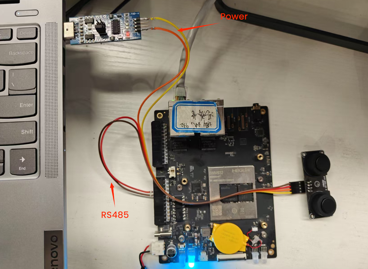
11.8.2 Hardware Connection
The sensor requires a minimum supply voltage of 5V. However, since the 5V pin and GND pin of the Rhino Pi A1 are still under debugging, an external power supply is used to power the sensor in this example.
Connect the RS485A and RS485B pins of the ultrasonic sensor to the RS485A and RS485B pins of the Rhino Pi A1 for communication.
11.8.3 Test
The Dianyingpu Ultrasonic Sensor requires manual sending of a distance measurement command to obtain a distance measurement result. One result will be obtained each time the command is sent.
1、Since the test tool minicom cannot be set to input hexadecimal data to control the sensor for distance measurement, a script can be written to convert the data format (from decimal to hexadecimal) and then send the data to the serial port device number for control. The content of the script is as follows:
#!/bin/bash
if [ "$#" -ne 2 ]; then
    echo "Usage: $0 [Serial Port Device] [Hexadecimal Data]"
    exit 1

fi
# Serial port device, e.g., /dev/ttyS2
SERIAL_PORT=$1

# Hexadecimal data, e.g., '1F2E3D4C'
HEX_DATA=$2

# Convert the hexadecimal data into a binary stream and send it to the serial port
printf "$HEX_DATA" | xxd -r -p > $SERIAL_PORT
2、Use the script to send the control command: sudo ./send_hex.sh /dev/ttyHS1 '01030100000185F6'
./send_hex.sh /dev/ttyHS1 '01030100000185F6'/dev/ttyHS1: RS485 device number of Rhino Pi A1
01030100000185F6: Used to read processed value data; there are also other commands. For details, please refer to the Dianyingpu product manual
3、Use the minicom tool to receive data in AidLux. (If not installed, install it via sudo apt update; apt install minicom). Open minicom with the command: sudo minicom -D /dev/ttyHS1 -b 9600 -H
sudo minicom -D /dev/ttyHS1 -b 9600 -H/dev/ttyHS1: RS485 device number of Rhino Pi A1
-b 9600: Set the baud rate to 9600 (the default baud rate of the sensor is 9600)
-H: Display data in hexadecimal format

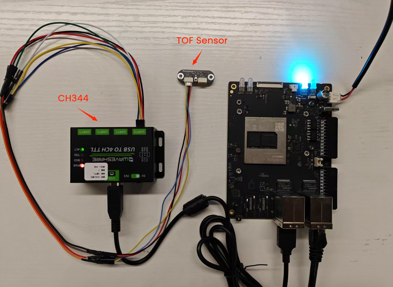
11.9 Nooploop TOF Sensor
- Official Documentation of the Kit: Nooploop TOFSense Series
11.9.1 Preparation
- Rhino Pi A1
- Nooploop TOFSense Series TOF Sensor
- USB to 4CH TTL Serial Port Expansion Device
- Several other connecting cables
11.9.2 Hardware Connection
Use the CH344 serial port device to connect the VCC, GND, TX, and RX of the TOF sensor to the VCC, GND, RX, and TX of any UART port on the CH344 device. The UART0 port is used in the current example.
11.9.3 Test
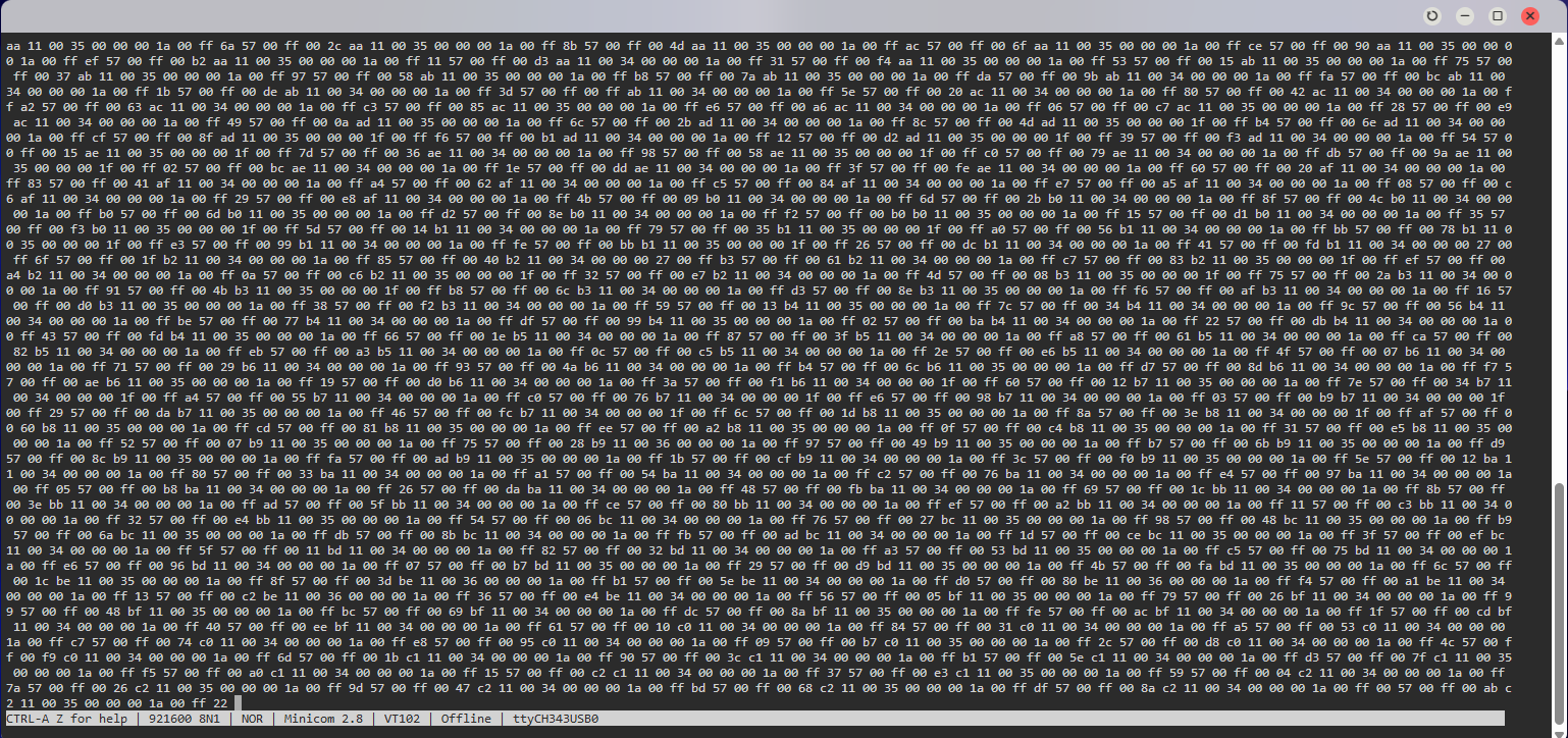
After the connection is completed, open the minicom tool in the AidLux terminal (if not installed, use the command sudo apt update; sudo apt install minicom to install it).
sudo apt update;sudo apt install minicomAfter installation, open the serial port:
sudo minicom -D /dev/ttyCH343USB0 -b 921600 -H
sudo minicom -D /dev/ttyCH343USB0 -b 921600 -HThe default baud rate of the TOF sensor is 921600, and it requires data to be displayed in hexadecimal format.
Note: If minicom only displays one line, please make the following settings:
Press CTRL-A + Z to enter the minicom settings page, then press W to enable line wrapping for display.
Below is an example of the received data.
11.10 SONBEST SM7820B Temperature and Humidity Sensor
- Official Documentation of the Kit:SM7820B
11.10.1 Preparation
- Rhino Pi A1
- SONBEST SM7820B Temperature and Humidity Sensor
- Several other connecting cables
- External 5V power supply
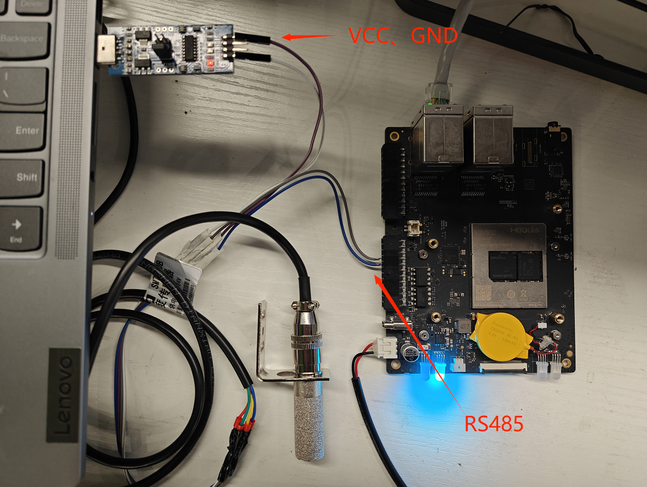
11.10.2 Hardware Connection
1、The sensor requires a minimum power supply of 5V. However, since the 5V pin and GND pin of Rhino Pi A1 are still under debugging, the sensor is powered by an external power supply in this example.
2、Connect the RS485A and RS485B pins of the temperature and humidity sensor to the RS485A and RS485B pins of Rhino Pi A1 for communication.
11.10.3 Test
The SONBEST Temperature and Humidity Sensor requires manual sending of a measurement command to obtain a measurement result. One measurement result is generated each time the command is sent.
1、Since the test tool minicom cannot be configured to input hexadecimal data for controlling the sensor's measurement, a script can be written to convert the data format (to hexadecimal) and then send the data to the serial port device number for control. The content of the script is as follows:
#!/bin/bash
if [ "$#" -ne 2 ]; then
    echo "Usage: $0 [Serial Port Device] [Hexadecimal Data]"
    exit 1

fi
# Serial port device, e.g., /dev/ttyS2
SERIAL_PORT=$1

# Hexadecimal data, e.g., '1F2E3D4C'
HEX_DATA=$2

# Convert the hexadecimal data into a binary stream and send it to the serial port
printf "$HEX_DATA" | xxd -r -p > $SERIAL_PORT
2、Use the script to send the control command: sudo ./send_hex.sh /dev/ttyHS1 '010300000002C40B'
./send_hex.sh /dev/ttyHS1 '010300000002C40B'/dev/ttyHS1: RS485 device number of Rhino Pi A1
010300000002C40B: Used to read temperature and humidity measurement data. There are also other commands (e.g., modifying the baud rate). For details, please refer to the SONBEST product manual
3、Use the minicom tool to receive data in AidLux. (If it is not installed, install it via sudo apt update; apt install minicom). Open minicom with the command: sudo minicom -D /dev/ttyHS1 -b 9600 -H
sudo minicom -D /dev/ttyHS1 -b 9600 -H/dev/ttyHS1: RS485 device number of Rhino Pi A1
-b 9600: Set the baud rate to 9600 (the default baud rate of the sensor is 9600)
-H: Display data in hexadecimal format
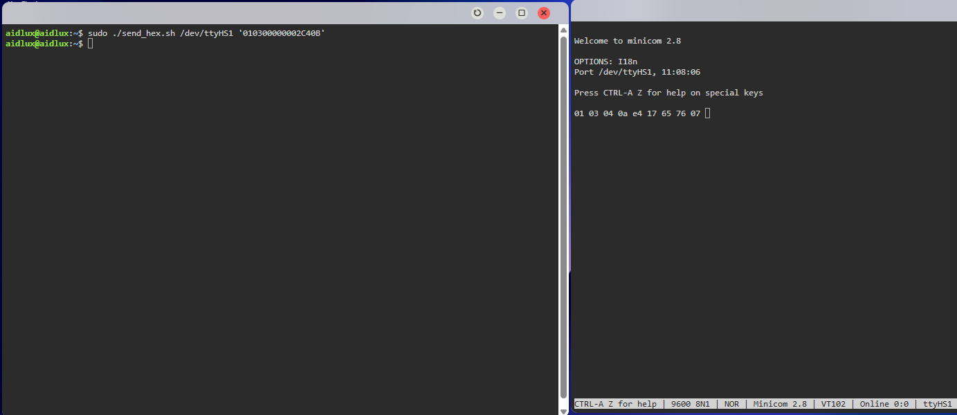
11.10.3 Result Analysis
After sending a query frame command to the temperature and humidity sensor, a response frame result will be returned: 01 03 04 0a e4 17 65 76 07.
The response format is shown in the figure below:

Among the data, Data 1 represents temperature and Data 2 represents humidity. According to the calculation method provided in the SONBEST SM7820B manual, take temperature calculation as an example:
Convert 0a e4 to a decimal number: 2788
The data scaling factor is 100. The actual temperature is calculated as 2788/100 = 27.88°C, which means the current indoor temperature is 27.88°C.