A6490BM1 Product User Manual
1. Product Overview
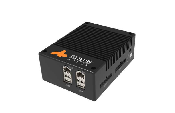
The APLUX AIBox A6490BM1 is a cost-effective edge computing product based on the Qualcomm QCS6490 platform, featuring 12 TOPS of AI computing power. The AIBox provides rich interfaces and supports multiple network connection modes to meet the connectivity needs of different application scenarios. It boasts powerful AI capabilities, with a large number of pre-installed scene algorithms and cases covering multiple fields such as smart parks, smart retail, smart security, smart kitchens, smart transportation, etc., enabling out-of-the-box use. It fulfills the intelligent needs of multiple industries and scenarios with low cost and high efficiency.
Product appearance:
2. Quick Start
2.1 Environment Preparation
Hardware Preparation:
- A computer with Windows 10 or higher
- A6490BM1
- USB Type-A to Type-C data cable
- Power adapter (12V 3A)
Software Preparation:
Download link for the software tool installation package
2.1.1 USB Driver Installation
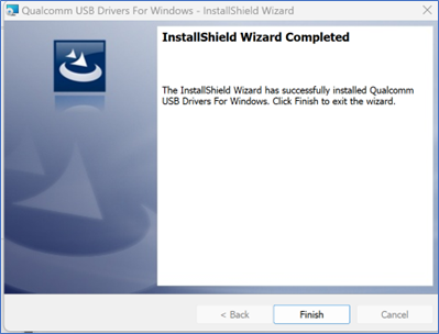
Unzip the file USB_Driver_qud.win.1.1_installer_10061.1.zip.
After unzipping, double-click the setup.exe program. Wait for the Qualcomm USB Drivers installation interface to appear, and click Next as prompted.
2.1.2 ADB Tool Installation
2.1.2.1 Unzip platform-tool.zip
- Unzip the platform-tools.zip file to the D drive.
2.1.2.2 Configure ADB Environment Variables
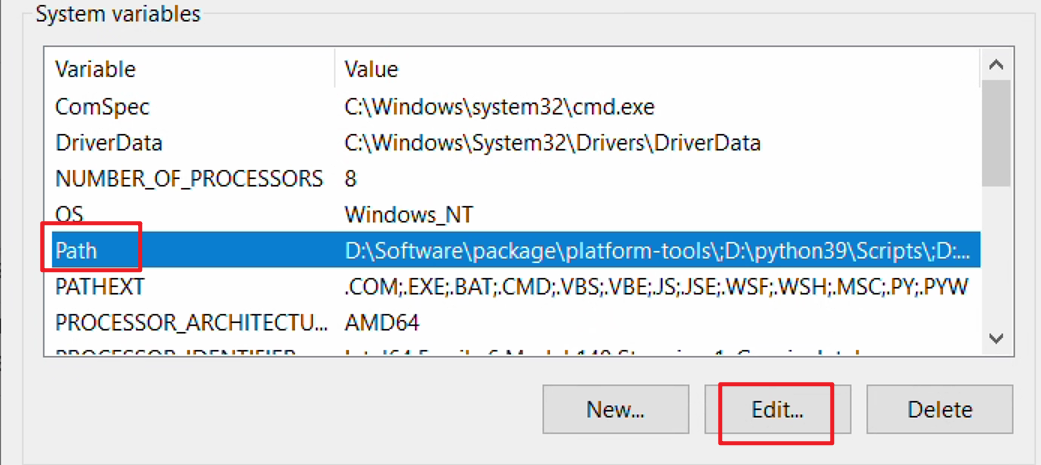
- Copy the path of the unzipped platform-tools folder.

- Right-click This PC and select Properties.
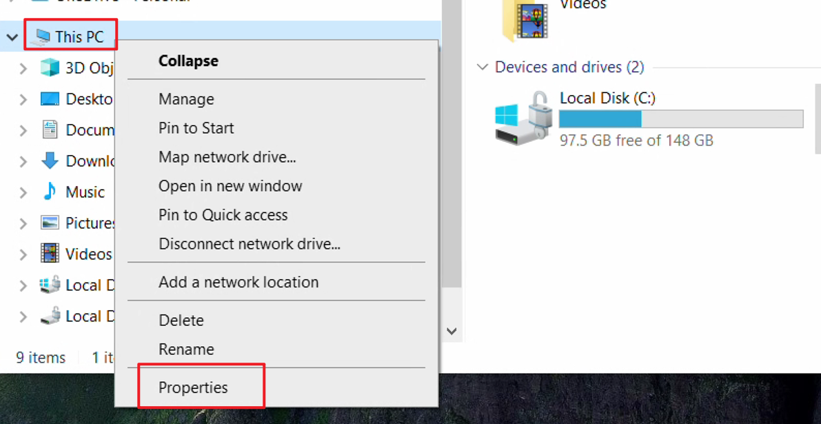
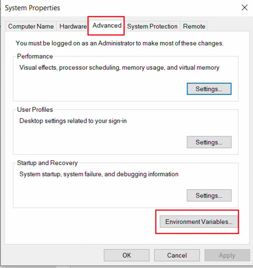
- In the pop-up settings window, click Advanced system settings.
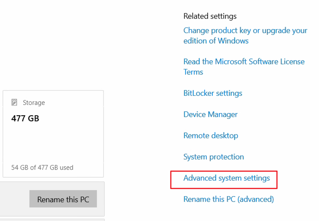
- In the System Properties window (Advanced tab), click Environment Variables.
- In the Environment Variables window, select the Path variable under System Variables and click Edit.
- In the Edit Environment Variable window, click New and add the platform-tools path copied earlier.
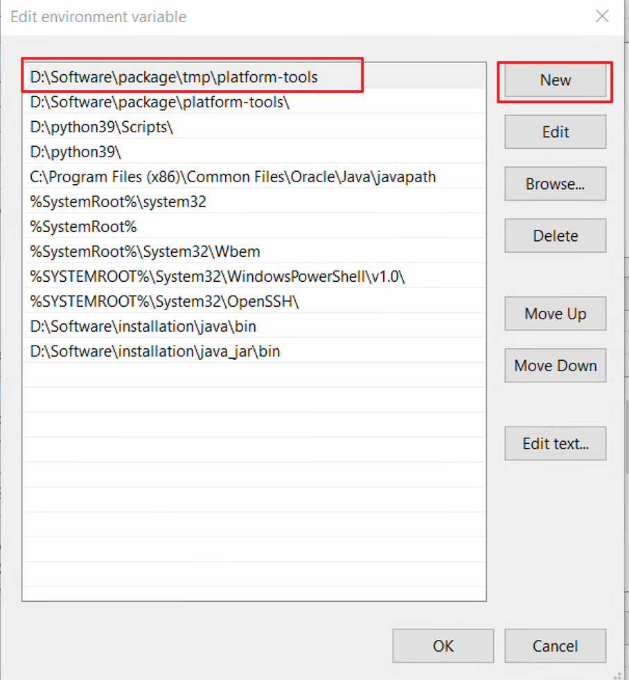
- Click OK sequentially to save the configured variables and exit.
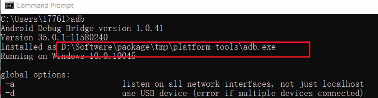
2.1.2.3 Verify ADB Environment Configuration
- Open the cmd window and enter adb. Check if the echo contains the ADB installation path copied in the 2.1.2.2 Configure ADB Environment Variables section.
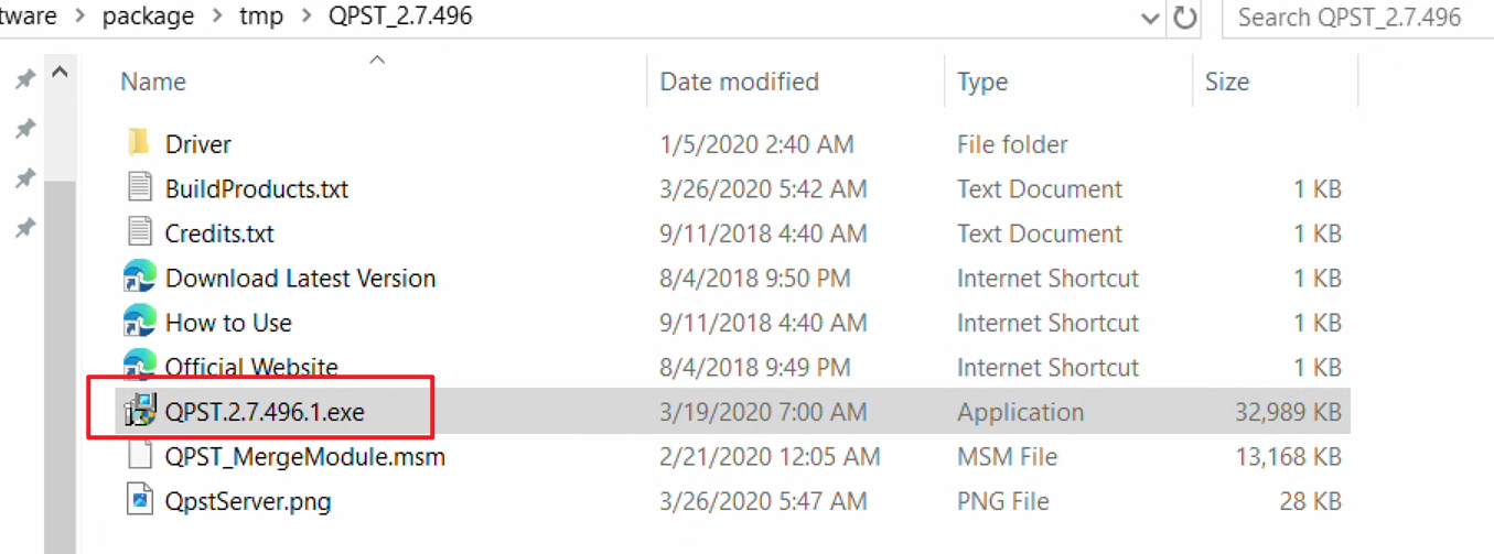
2.1.3 Flashing Tool Installation
Unzip the QPST_2.7.496.zip file to the current folder.
Go to the unzipped QPST_2.7.496 directory and double-click the QPST.2.7.496.1.exe program to start installation.
Follow the prompts and keep clicking Next to complete the installation.
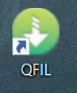
Default installation path after completion: C:\Program Files (x86)\Qualcomm\QPST\bin.
Enter this directory and send the QFIL.exe program to the desktop.
The desktop icon is as follows:
2.2 Device Startup
2.2.1 Power Cable Connection
- Connect the DC port of the board to a DC 12V/3A power adapter. The device will start automatically by default when powered on. Observe the indicator lights during startup: the PWR light blinks green (starting up) and then stays solid green along with the CAM light (startup complete).
2.2.2 Type-C Cable Connection
Plug the Type-A end of the cable into a USB 3.0 port on your Windows PC, and connect the Type-C end to the Type-C port on the AIBox.
On your Windows PC, press Win+R to open the Run dialog, type cmd, and hit Enter to open the Command Prompt. Then execute the following command:
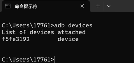
adb devices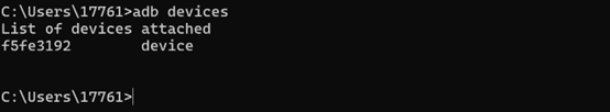
If the device is listed as shown above, it indicates successful connection and startup. Developers can then access the AidLux system on the AIBox according to their specific development environment.
3. System Login
Due to the diverse development environments of developers, we recommend different ways to log into the AidLux system for the following scenarios, which developers can use as needed.
3.1 Direct Device Connection via ADB
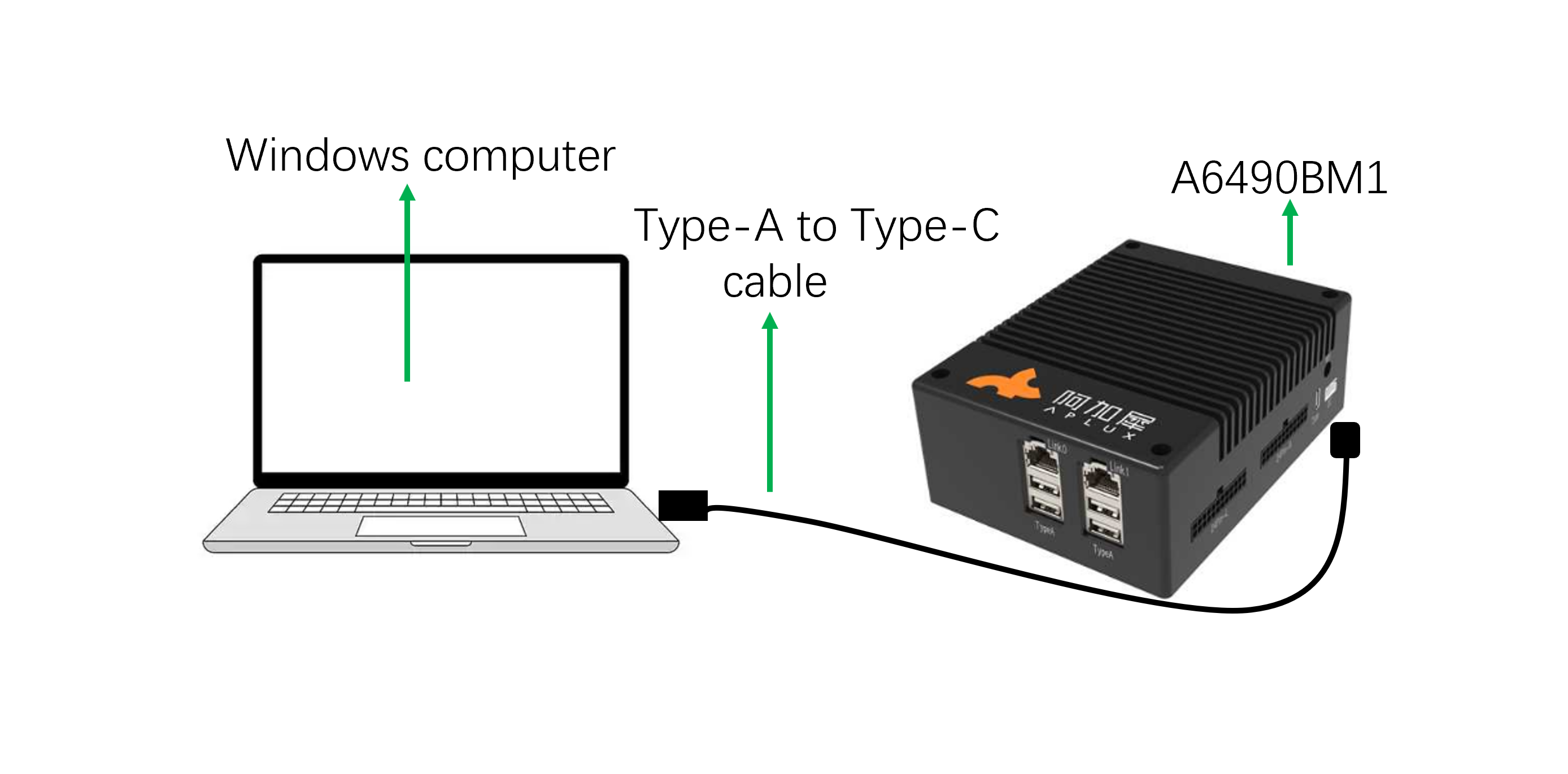
When developers only have a Windows computer and a Type-C cable, they can connect the Windows computer to the AIBox via the Type-C cable and use the ADB (Android Debug Bridge) tool to access the AidLux system by following these steps:
Network Diagram:
3.1.1 Directly enter the AidLux system
Once connected to the device via ADB, access the AidLux system as follows:
- Open a terminal window on Windows, execute the command adb root to obtain root privileges, then run adb shell to log into the host system.
adb root
adb shell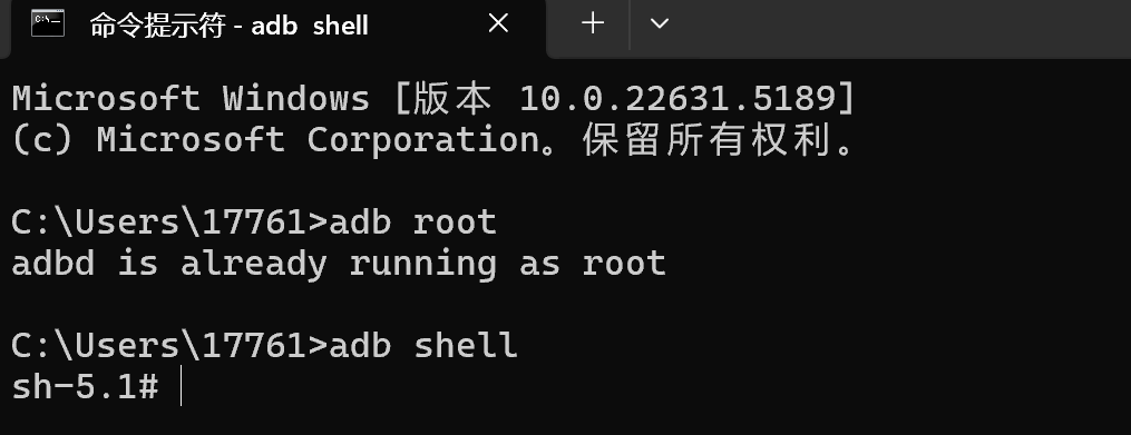
- Then execute the command docker exec -it aidlux bash to log into the AidLux system.
docker exec -it aidlux bash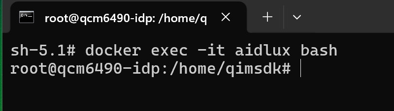
💡Note
In this scenario, you cannot access the Desktop of the AidLux system and can only develop in the command-line interface.
By following the steps above, you can access the AidLux system.
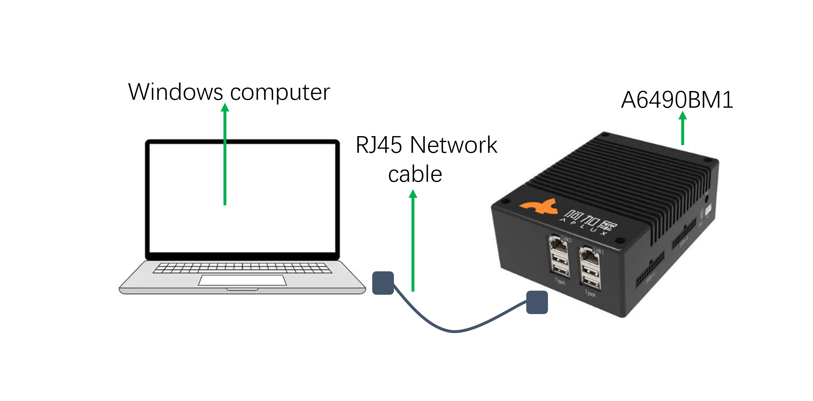
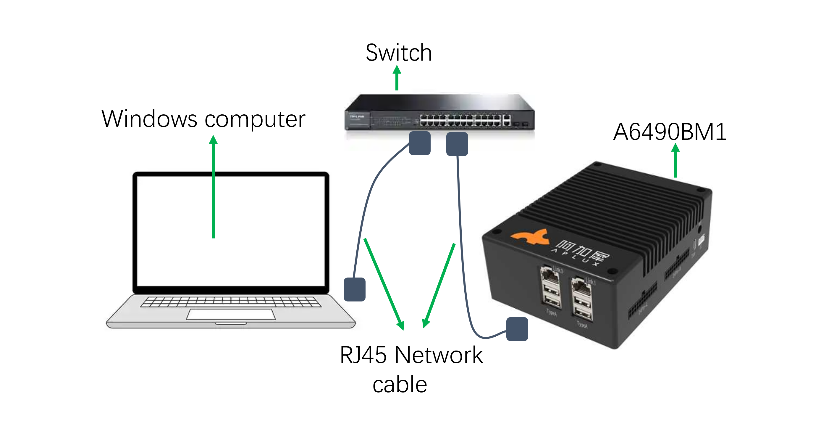
3.2 Direct Device Connection via Ethernet Cable
When developers have only one Windows computer and an Ethernet cable but do not want to access the AidLux system via ADB, they can configure a static IP to access the system as follows:
Network Diagram:
💡Note
The device's Link0 port is a 2.5G Ethernet port, and Link1 is a 1G Ethernet port. Either port can be used.
If Link0 (left port) is used, the corresponding network interface name in the system is eth0; if Link1 (right port) is used, the name is eth1.
3.2.1 Configure Static IP for the Windows Computer
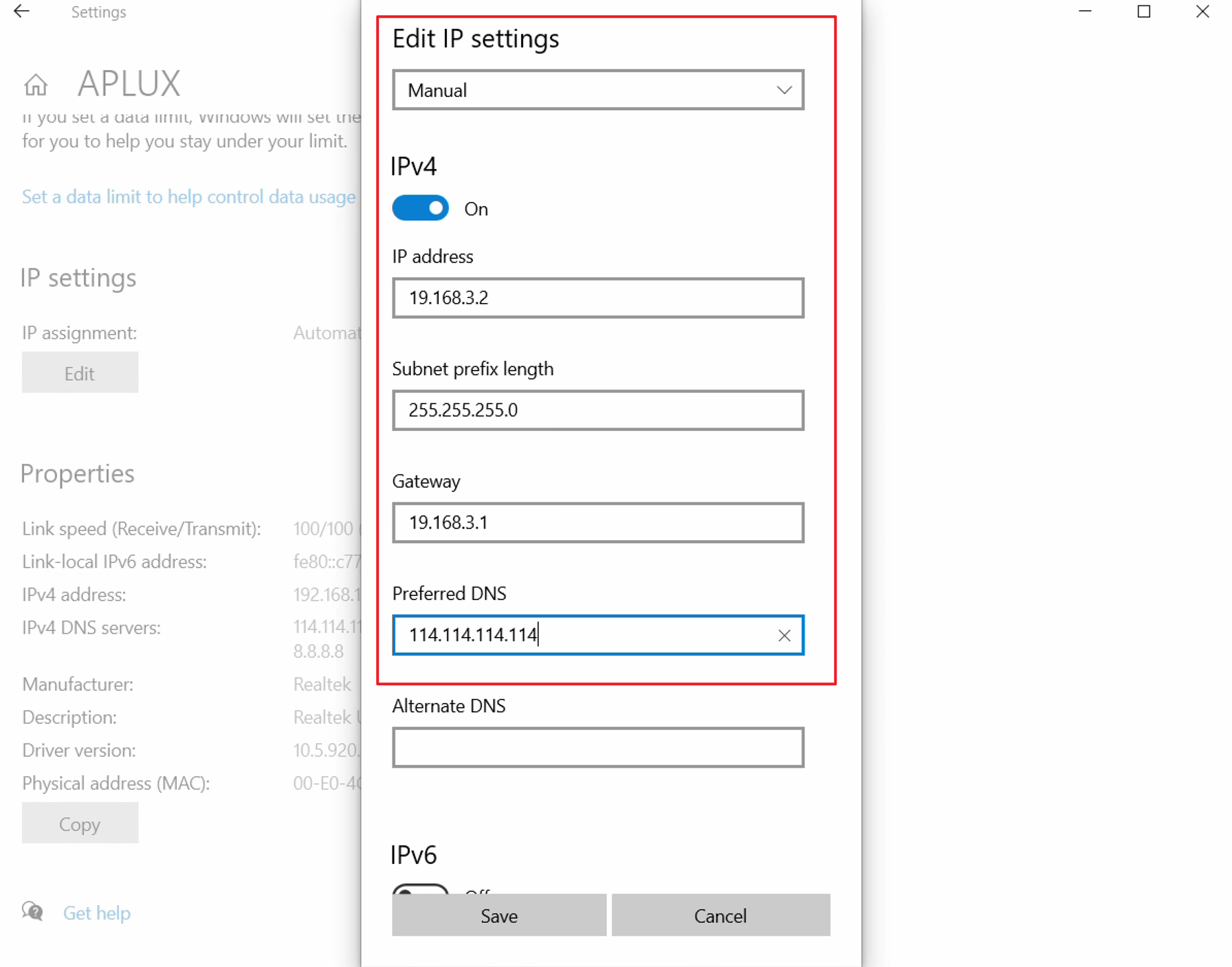
- Press the Win+X key combination to open the system shortcut menu, select Network & Internet, and click Ethernet in the pop-up window.
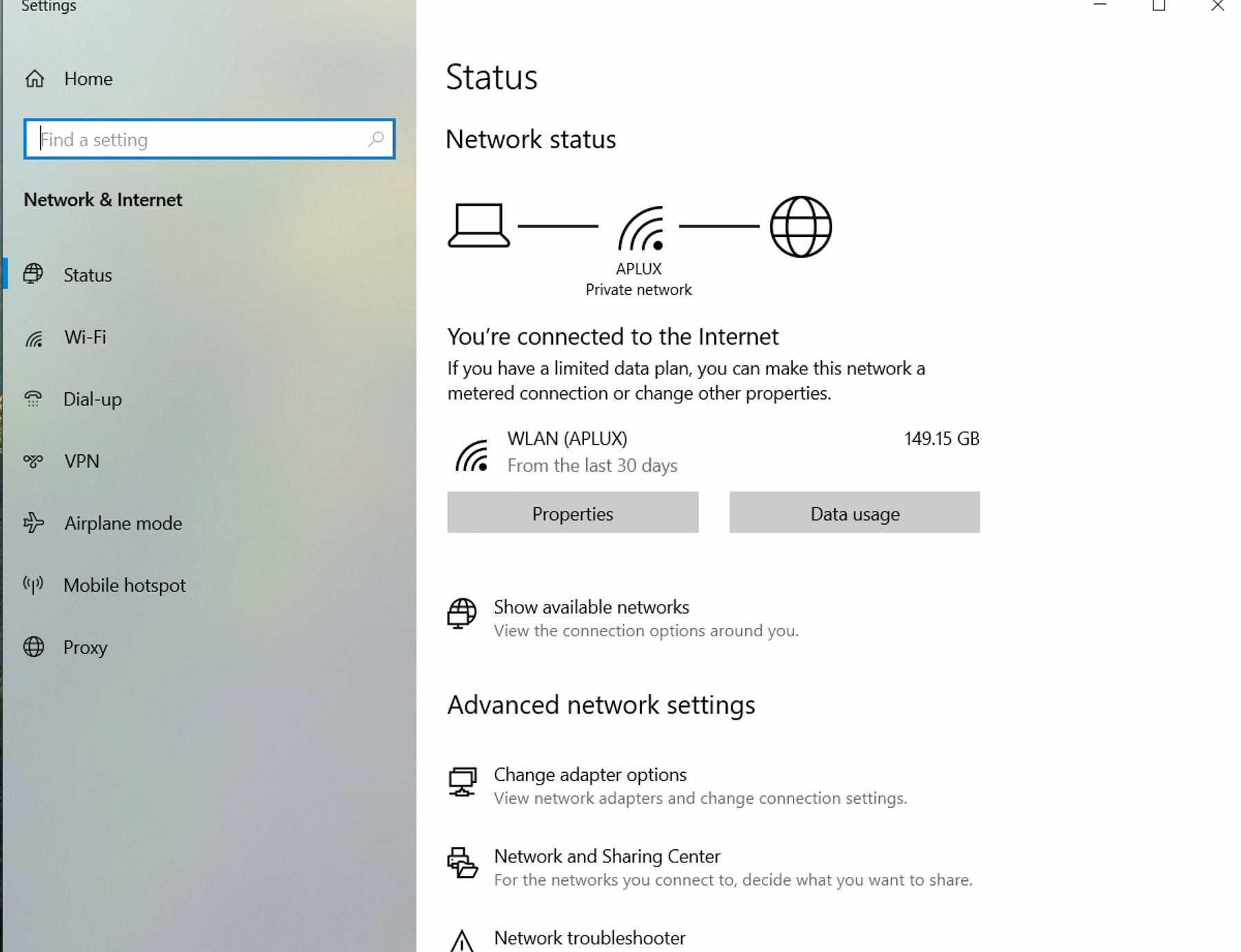
- In the Ethernet window, find the IP assignment section and click the Edit button to configure a static IP.
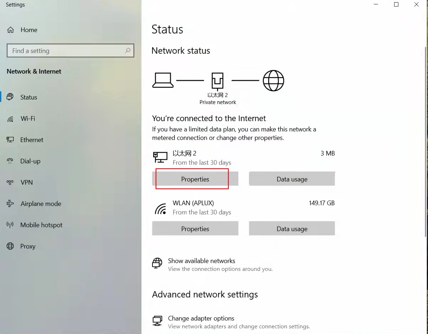
- In the IP settings, select Manual, enable the IPv4 toggle, and edit the IPv4 address, subnet mask, etc., as needed.
💡Note
The IP address, subnet mask, gateway, and DNS information in the example image are for reference only. Configure them according to your actual network environment.
- Click Save to apply the network configuration.
3.2.2 Configure a static IP for AIBox
The A6490BM1 device has a default static IP configuration. To reconfigure a different static IP, delete the original configuration and restart the device:
Open a terminal window on Windows (press Win+R, type cmd, and press Enter), then run:
adb shell- Delete the static IP configuration:
nmcli connection delete eth1- Restart the device to apply changes:
reboot- Configure a static IP in the same network segment as the Windows computer:
 nmcli con add type ethernet ifname eth1 con-name eth1 \
                    ipv4.addresses "192.168.2.123" \
                    ipv4.gateway "192.168.2.1" \
                    ipv4.dns "223.6.6.6,8.8.8.8" \
                    ipv4.method manual
💡Note
The IP address and subnet mask in the example are for reference only. Adjust them according to your actual network. Restart the device after configuration.
3.2.3 Verify Network Configuration
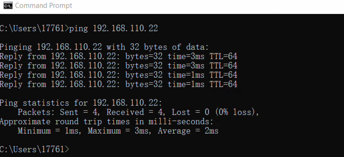
- After configuring IP addresses for both the Windows computer and AIBox, test connectivity by pinging the AIBox from Windows. If the ping is successful, the configuration is valid. If not, check the network settings.
3.2.4 Remote Login via Browser (Recommended)
Tip
This method allows direct login to the AidLux system's Desktop.
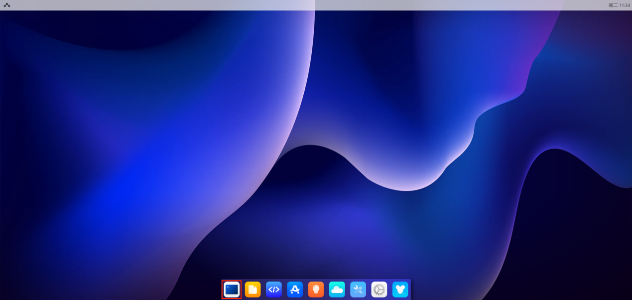
- Enter the URL http://AIBox_IP:8000/login in a browser (replace AIBox_IP with the actual IP configured in the previous steps).Username/Password: aidlux/aidlux

- After logging in, click the first icon labeled Terminal at the bottom to use the command line.
3.2.5 Remote Login via SSH
Tip
This method allows remote login to AidLux via SSH but does not provide access to the Desktop.
- Open a terminal window on Windows and execute(Replace AIBox_IP with the device’s actual IP address.):
ssh aidlux@192.168.111.122 -p 2222AidLux user: aidlux/aidlux
root user: root/P@ssw0rd
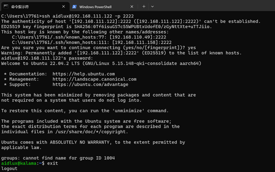
Follow the steps above to access the AidLux system.
3.3 Wired LAN Connection
When the development environment has a local area network (LAN) with a DHCP server to assign IP addresses to connected devices, use the following steps to connect to and access the AidLux system:
Network Diagram:
💡Note
The device's Link0 port is a 2.5G Ethernet port, and Link1 is a 1G Ethernet port. Either port can be used.
3.3.1 Obtain AIBox’s DHCP IP
The A6490BM1 device has a default static IP. To use DHCP, delete the static IP configuration and restart the device:
- Open a terminal on Windows and run:
adb shell- Delete the static IP configuration:
nmcli connection delete eth0- Restart the device:
reboot- After rebooting, use ADB to enter the AIBox’s host system and run ifconfig eth0 (replace eth0 with eth1 if using Link1) to check the obtained IP address.
adb shell
ifconfig eth0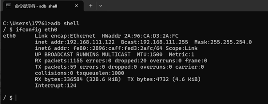
3.3.2 Verify Network Configuration
- Ping the AIBox from Windows to check connectivity. A successful ping indicates valid configuration.
3.3.3 Remote Login via Browser (Recommended)
Tip
This method allows direct login to the AidLux system's Desktop.
- Enter the URL http://AIBox_IP:8000/login in a browser (replace AIBox_IP with the actual IP configured in the previous steps).Username/Password: aidlux/aidlux
- After logging in, click the first icon labeled Terminal at the bottom to use the command line.
3.3.4 Remote Login via SSH
Tip
This method allows remote login to AidLux via SSH but does not provide access to the Desktop.
- Open a terminal window on Windows and execute(Replace AIBox_IP with the device’s actual IP address.):
ssh aidlux@192.168.111.122 -p 2222AidLux user: aidlux/aidlux
root user: root/P@ssw0rd
Follow the steps above to access the AidLux system.
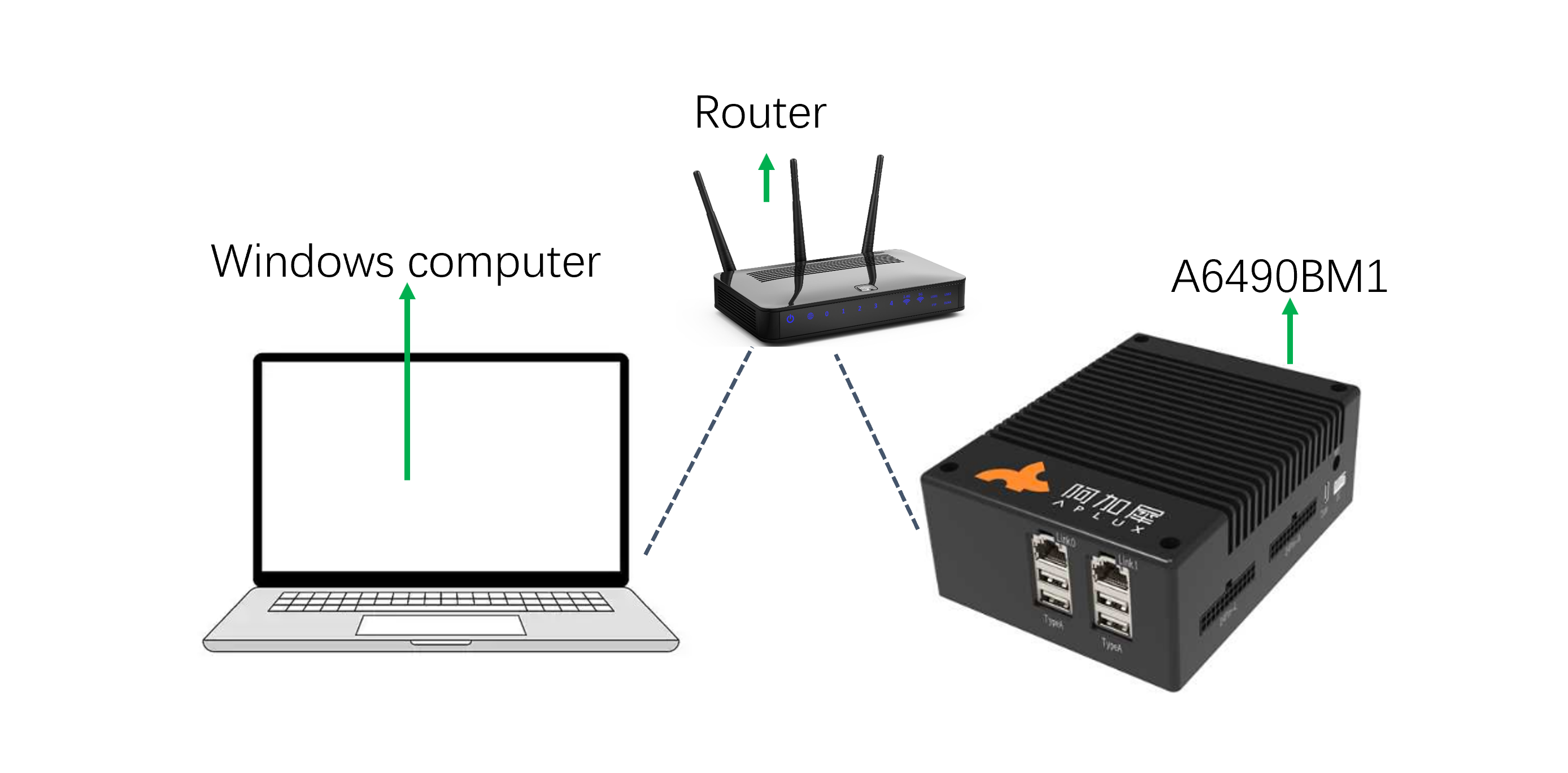
3.4 Wireless LAN Connection
The AIBox supports Wi-Fi connectivity. To connect to the AIBox via a LAN Wi-Fi network, follow these steps:
Network Diagram:
3.4.1 Connect/Disconnect to Wi-Fi on AIBox
- Open a terminal on Windows and run:
adb shell- Scan for available Wi-Fi networks:
nmcli dev wifi list 2>&1 | less💡Note
Use the up/down arrow keys to view all APs. Press CTRL+C to exit the scan interface.
- Connect to a specific AP:
nmcli dev wifi connect WiFi-SSID password WiFi-password💡Note
Replace WiFi-SSID with the network name and WiFi-password with the password.
- Check the connection status:
nmcli general status- View the assigned IP address:
ifconfig wlan0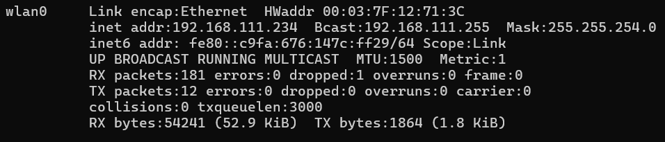
- Disconnect from the AP:
nmcli con down ssid/uuid3.4.2 Verify Network Configuration
- After configuring IP addresses for both the Windows computer and AIBox, test connectivity by pinging the AIBox from Windows. If the ping is successful, the configuration is valid. If not, check the network settings.
3.4.3 Remote Login via Browser (Recommended)
Tip
This method allows direct login to the AidLux system's Desktop.
- Enter the URL http://AIBox_IP:8000/login in a browser (replace AIBox_IP with the actual IP configured in the previous steps).Username/Password: aidlux/aidlux
- After logging in, click the first icon labeled Terminal at the bottom to use the command line.
3.4.4 Remote Login via SSH
Tip
This method allows remote login to Aidlux via SSH but does not provide access to the Desktop.
- Open a terminal window on Windows and execute(Replace AIBox_IP with the device’s actual IP address.):
ssh aidlux@192.168.111.122 -p 2222AidLux user: aidlux/aidlux
root user: root/P@ssw0rd
Follow the steps above to access the AidLux system.
4. Hardware Interfaces
4.1 Description of Hardware External Interfaces
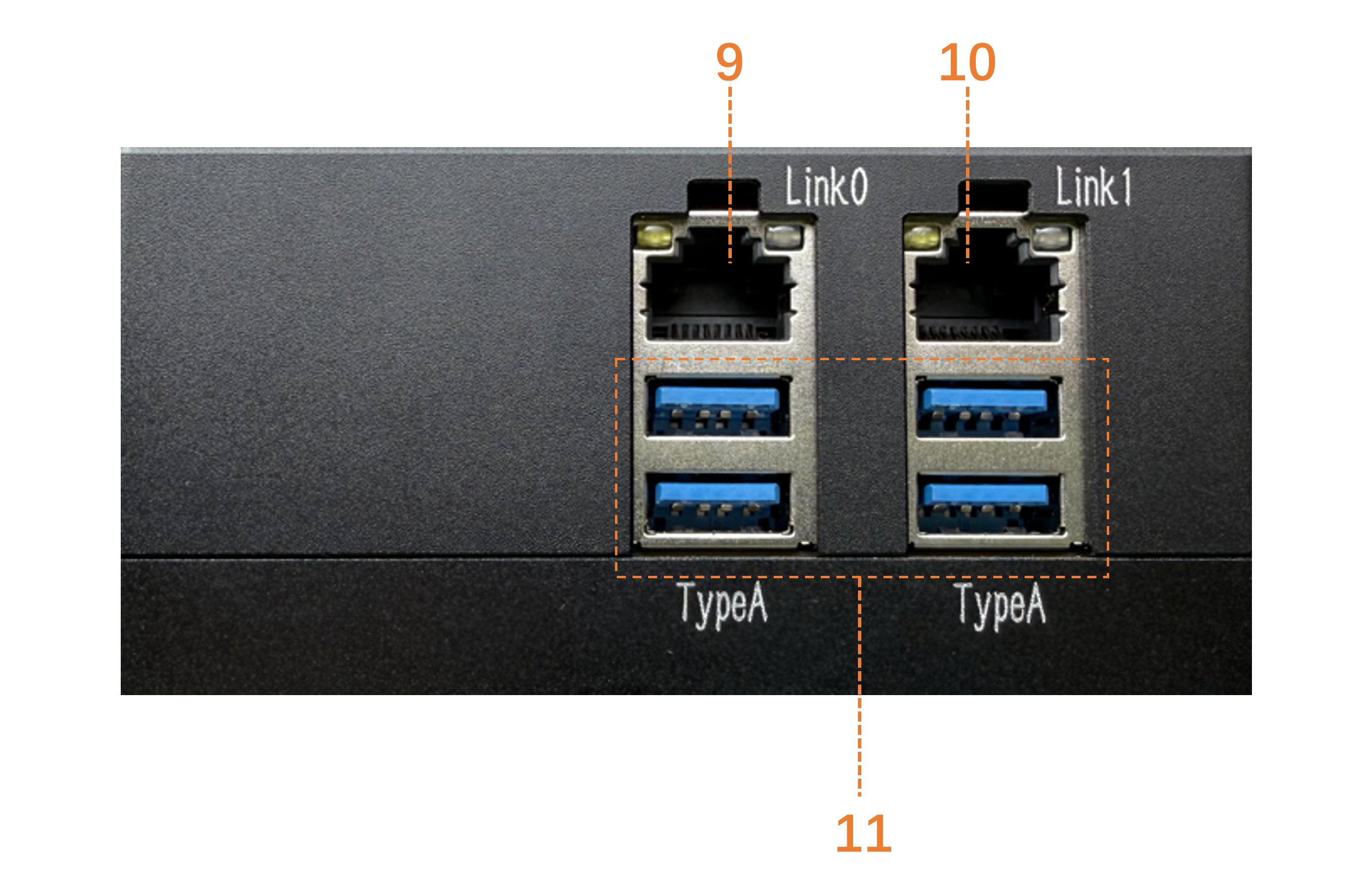
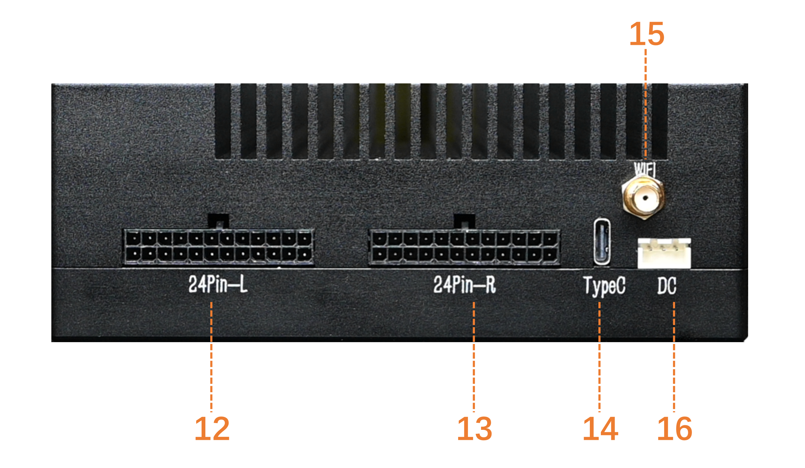
Hardware External Interface Diagram:

Functions of Hardware External Interfaces:
| Interface Number | Interface Name | Function Description |
|---|---|---|
| 1 | VOL- | Volume Down Button |
| 2 | UFS Light | Disk Activity Indicator Light |
| 3 | RAM Light | Memory Activity Indicator Light |
| 4 | TF | TF Card Slot |
| 5 | VOL+ | Volume Up Button |
| 6 | PWR Key | Power Button |
| 7 | PWR Light | Power Indicator Light |
| 8 | CAM Light | Camera Indicator Light |
| 9 | LINK0 | 2.5G Ethernet Port |
| 10 | LINK1 | 1G Ethernet Port |
| 11 | Type-A | x4 Type-A Interfaces |
| 12 | 24Pin-L | 24-Pin Interface (Left) |
| 13 | 24Pin-R | 24-Pin Interface (Right) |
| 14 | Type-C | Type-C Interface |
| 15 | WIFI/BT ANT | WIFI/BT Antenna Interface |
| 16 | DC | DC Power Interface |
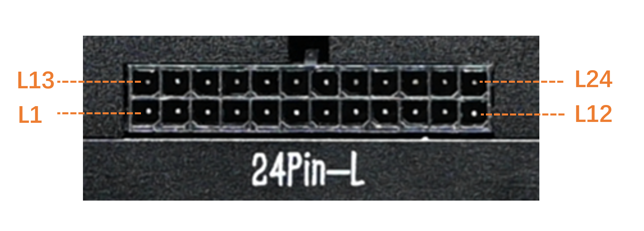
Diagram of 24Pin-L Interface:
Functions of 24Pin-L Interfaces:
| Pin Number | Definition | Attribute | Description |
|---|---|---|---|
| L1 | OUT_3.3V | Output | 3.3V Output |
| L2 | GND | GND | Ground |
| L3 | DBG_UART_TX_3V3 | Output | Debug UART Output |
| L4 | UART4_RXD_3V3 | Input | UART Input |
| L5 | GPIO5/OUT | I/O | 3.3V GPIO |
| L6 | I2S0_SCK_3V3 | Output | 3.3V I2S Clock |
| L7 | I2S0_WS_3V3 | Output | 3.3V I2S Chip Select |
| L8 | I2S0_DATA0_3V3 | I/O | 3.3V I2S Data 0 |
| L9 | I2S0_DATA1_3V3 | I/O | 3.3V I2S Data 1 |
| L10 | GND | GND | Ground |
| L11 | RS232_1_TX | Output | RS232 Output |
| L12 | GPIO40/OUT_GPIO_INT | I/O | 3.3V GPIO with Interrupt |
| L13 | GPIO87/OUT_GPIO_INT | I/O | 3.3V GPIO with Interrupt |
| L14 | RS232_1_RX | Input | RS232 Input |
| L15 | GND | GND | Ground |
| L16 | SPI1_CS_N_3V3 | Output | 3.3V SPI Chip Select |
| L17 | SPI1_CLK_3V3 | Output | 3.3V SPI Clock |
| L18 | SPI1_MOSI_3V3 | Output | 3.3V SPI MOSI |
| L19 | SPI1_MISO_3V3 | Output | 3.3V SPI MISO |
| L20 | GPIO199/OUT | Output | 3.3V GPIO |
| L21 | UART4_TXD_3V3 | Output | UART Output |
| L22 | DBG_UART_RX_3V3 | Input | Debug UART Input |
| L23 | GND | GND | Ground |
| L24 | 5V | Output | 5V Output |
Diagram of 24Pin-R Interface:
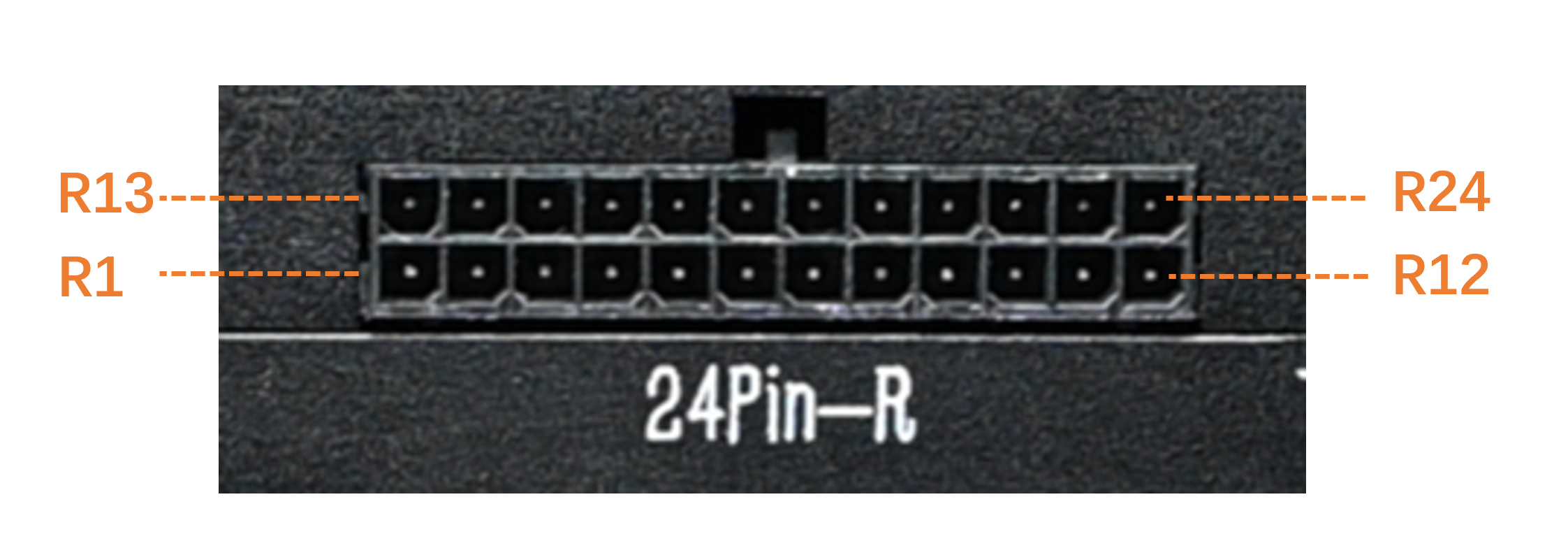
Functions of 24Pin-R Interfaces:
| Pin Number | Definition | Attribute | Description |
|---|---|---|---|
| R1 | RS232_TX | Output | RS232 Output |
| R2 | GPIO4/OUT | I/O | 3.3V GPIO |
| R3 | GND | GND | Ground |
| R4 | SPK_P | Output | Speaker Positive Output |
| R5 | SPK_N | Output | Speaker Negative Output |
| R6 | GND | GND | Ground |
| R7 | LINEOUT1+ | Output | Optocoupler Output 1 (Voltage set by PIN8) |
| R8 | LINEOUT1_POWER | Input | Optocoupler Output Voltage 1 |
| R9 | LINEOUT2+ | Output | Optocoupler Output 2 (Voltage set by PIN17) |
| R10 | GND | GND | Ground |
| R11 | CAN_H0 | Output | CAN0 High Output |
| R12 | CAN_H1 | Output | CAN1 High Output |
| R13 | CAN_L1 | Output | CAN1 Low Output |
| R14 | CAN_L0 | Output | CAN0 Low Output |
| R15 | GND | GND | Ground |
| R16 | LINELN2+ | Output | Optocoupler Input 2 |
| R17 | LINEOUT2_POWER | Output | Optocoupler Output Voltage 2 |
| R18 | LINELN1+ | Output | Optocoupler Input 1 |
| R19 | GND | GND | Ground |
| R20 | RS485_B | Output | RS485 B Line |
| R21 | RS485_A | Output | RS485 A Line |
| R22 | GND | GND | Ground |
| R23 | GND | GND | Ground |
| R24 | RS232_RX | Input | RS232 Input |
4.2 Description of Hardware Board Interfaces
Hardware Board Interface Diagram:
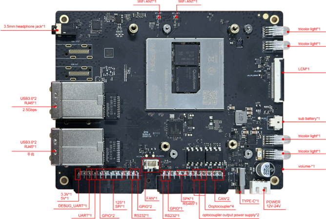
Hardware Board Interface Table:
| Interface | Quantity/Specification |
|---|---|
| C-PHY-Camera Module | x 1, IMX586(48M) |
| D-PHY-Camera Module | x 1, IMX577(12M) |
| Binocular Structured Light Camera Module | x 1, IMX577(12M)+2*OV9282(2M) |
| LCD | x 1, MIPI interface, default ST7703, 720*1280 (customizable FPC adapter for higher resolution) |
| USB Type-A | x 4, USB3.0, host mode (total bandwidth: 5Gbps for 4 ports) |
| USB Type-C | x 1, USB3.0,supports DP1.4 |
| LAN(RJ45) | x 2, one port at 2.5Gbps, one port at 1Gbps |
| CAN | x 2 |
| RS232 | x 2,for serial communication |
| RS485 | x 1,for serial communication |
| Optocoupler Input | x 2,5~30V |
| Optocoupler Output | x 2,5~30V |
| TF 卡 | x 1 |
| I2S | x 1,3.3V |
| SPI | x 1,3.3V |
| GPIO | x 5,3.3V |
| UART | x 1,3.3V |
| Debug UART | x 1,for debugging |
| Headphone Jack | x 1,3.5mm |
| SPK | x 1,1.65W |
| Tri-color LED | x 4,tri-color indicator lights: red, green, blue |
| KEY | x 3,power/vol+/vol- |
| Power Interface (12V/24V) | x 1, external adapter power supply |
| RTC | x 1,CR2032(225mAh) |
| ANT | x 2,WIFI/BT 天线 |
| Operating Temperature | -30℃~+75°C |
| Storage Temperature | -40°C ~ +90°C |
| Dimensions | 100 x 130 x 39.25mm |
5. File Transfer
5.1 File Transfer via SCP
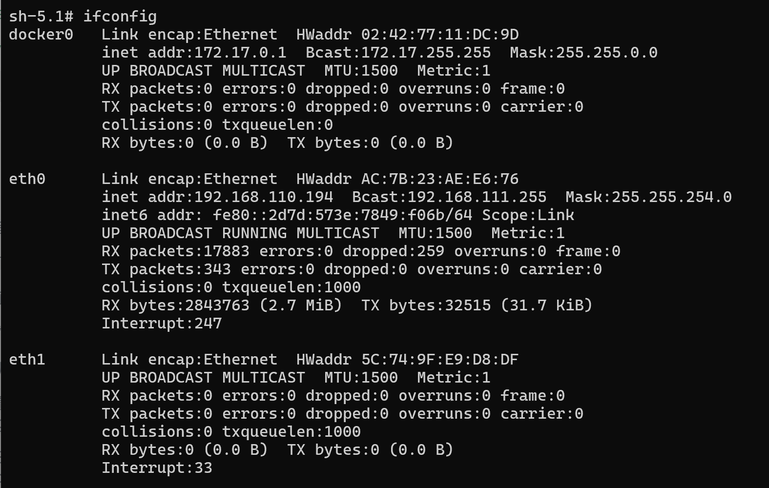
SCP transfer requires the A6490BM1 to be connected to the network. If the AIBox's IP address is 192.168.110.194, enter the following commands in the terminal:
Tip
Enter ifconfig in the AIBox's terminal to check the current IP address.
- To upload the file test.txt to the /home/aidlux/ directory from a PC terminal, use:
scp -r -P2222 .\test.txt aidlux@192.168.110.194:/home/aidlux/- To download a file from the AIBox to the PC's current directory, use:
scp -r -P2222 aidlux@192.168.110.194:/home/aidlux/test.txt ./5.2 File Transfer via AidLux File Browser
File transfer via the AidLux file browser requires the A6490BM1 to be connected to the network. If the AIBox's IP address is 192.168.110.194, follow these steps:
Tip
Enter ifconfig in the AIBox's terminal to check the current IP address.
- Enter the URL http://192.168.110.194:8000/ in a browser to log into the AidLux desktop environment (password: aidlux). After logging in, click the file browser icon to proceed.
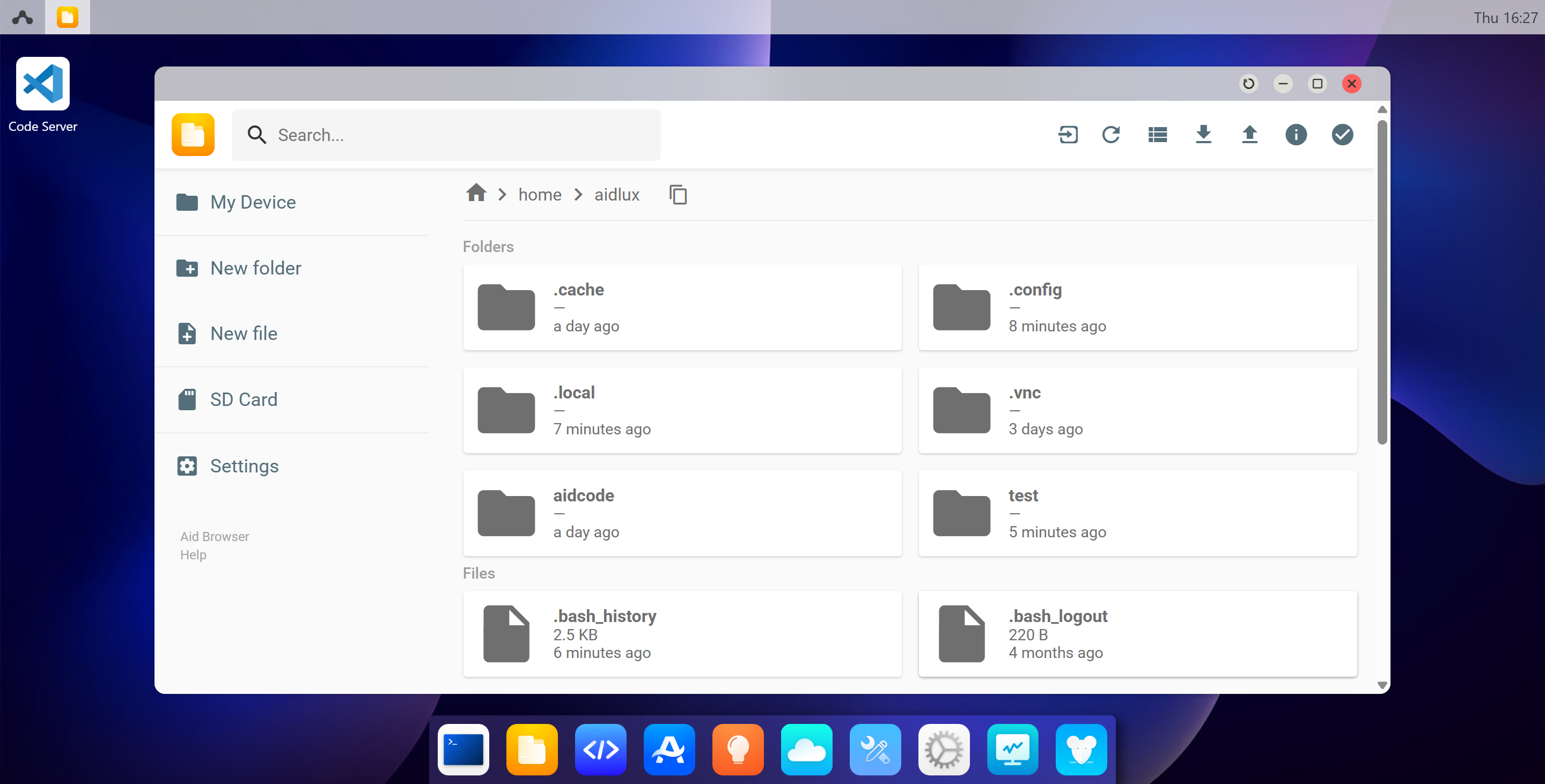
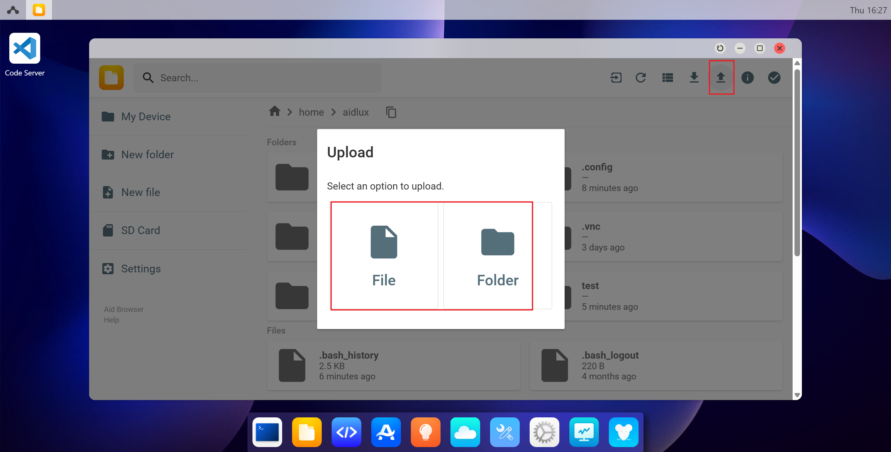
- Click the Upload button in the upper right corner to transfer files or directories to the /home/aidlux/ directory.
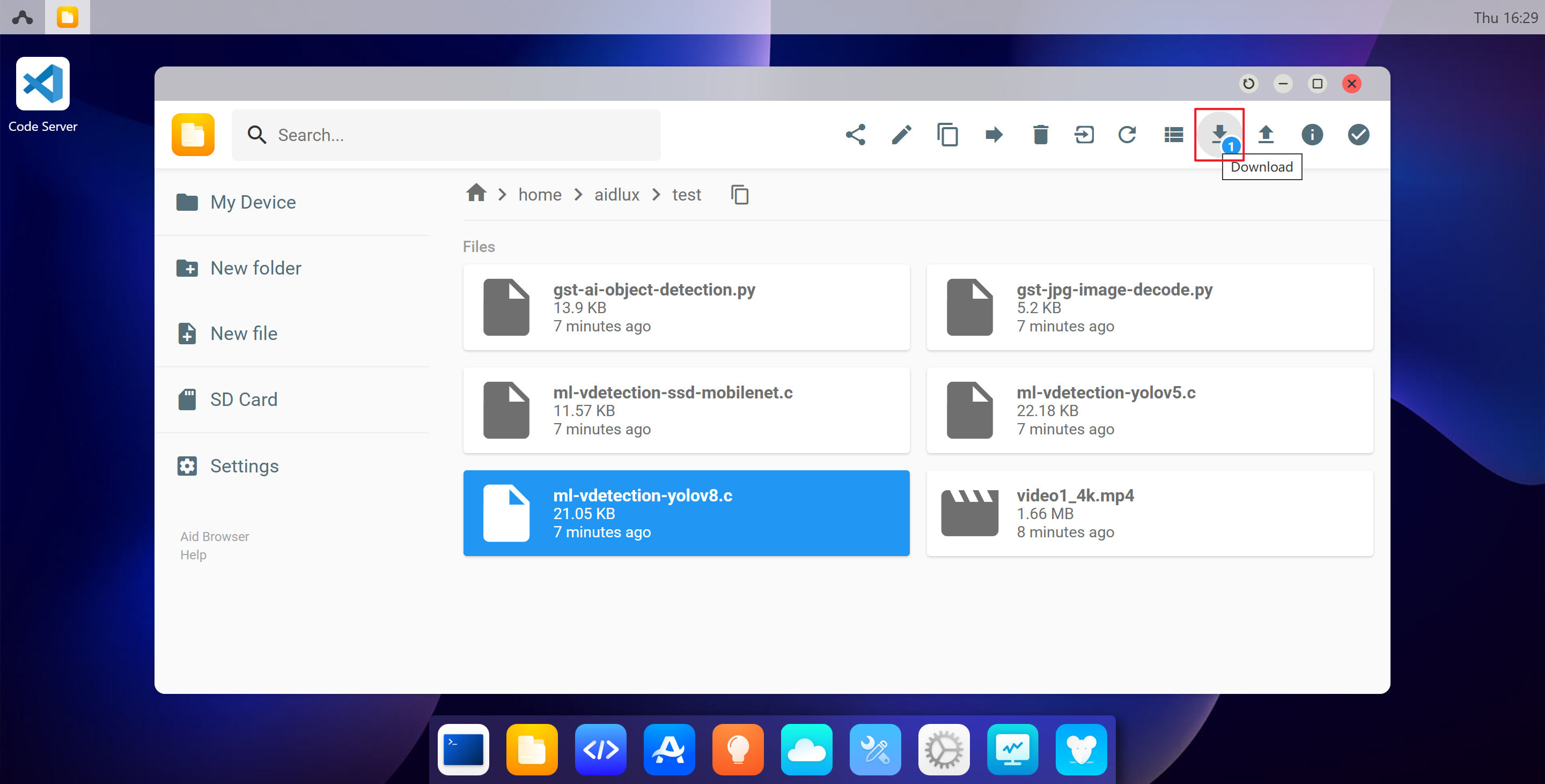
- Click the Download button in the upper right corner to download files or directories from the /home/aidlux/ directory to your local machine.
6. Model Farm
APLUX has established the Model Farm platform.The Model Farm contains hundreds of mainstream open-source models with different functions, which are adapted and optimized for different hardware platforms. Developers can quickly complete evaluations on the A6490BM1 without investing significant costs or long waiting times. For usage guidance on the Model Farm, please refer to theModel Farm User Guide document.
7. AI Function Usage
APLUX has developed a complete set of edge AI development toolkits to help developers accelerate the deployment of AI applications, covering everything from underlying systems to upper-layer application-level SDKs. For details, see the Developer Guide
7.1 Aidlite SDK Usage Examples
7.1.1 SDK&API Documentation
7.1.2 aidlite_qnn
# Enter the project directory:
cd /usr/local/share/aidlite/examples/aidlite_qnn229/python

# Run the test project script:
sudo python3 qnn_yolov5_multi.py

# Notes: 1. The sudo password is "aidlux". 2. This example only uses the DSP.# Enter the project directory:
cd /usr/local/share/aidlite/examples/aidlite_qnn229/cpp
# Compile the executable:
sudo mkdir build && cd build
sudo cmake ..
sudo make
# Run the test project script:
sudo ./qnn_yolov5_multi 4
# Notes: 1. The sudo password is "aidlux". 2. This example only uses the DSP.7.1.3 aidlite_snpe
# Enter the project directory:
cd /usr/local/share/aidlite/examples/aidlite_snpe223/python

# Run the test project script:
sudo python3 snpe2_yolov5_multi.py 3

# Notes: 1. The sudo password is "aidlux". 2. This example only uses the DSP.# Enter the project directory:
cd /usr/local/share/aidlite/examples/aidlite_snpe223/cpp
# Compile the executable:
sudo mkdir build && cd build
sudo cmake ..
sudo make
# Run the test project script:
sudo ./snpe2_yolov5_multi 4
# Notes: 1. The sudo password is "aidlux". 2. This example only uses the DSP.7.1.4 aidlite_tflite
# Enter the project directory:
cd /usr/local/share/aidlite/examples/aidlite_tflite/python

# Run the test project script:

# Using CPU:
sudo python3 tflite_yolov5_multi.py 1

# Using GPU:
sudo python3 tflite_yolov5_multi.py 2

# Notes: 1. The sudo password is "aidlux"# Enter the project directory:
cd /usr/local/share/aidlite/examples/aidlite_tflite/cpp
# Compile the executable:
sudo mkdir build && cd build
sudo cmake ..
sudo make
# Run the test project script:
# Using CPU:
sudo ./snpe2_yolov5_multi 1
# Using GPU:
sudo ./snpe2_yolov5_multi 2
# Using DSP:
sudo ./snpe2_yolov5_multi 3
# Notes: 1. The sudo password is "aidlux"7.2 Aidstream-gst SDK Usage Examples
7.2.1 Aidstream-gst SDK Documentation
7.2.2 Pure Codec Example
# Enter the project directory:
cd /usr/local/share/aidstream-gst/example/cxx

# Compile the executable:
sudo mkdir build && cd build
sudo cmake -DV4L2=ON ..
sudo make

# Run the test project script:
./start 1

# Notes: 1. The sudo password is "aidlux". 2. Modify the input/output addresses in the configuration file /usr/local/share/aidstream-gst/conf/aidstream-gst.conf.
7.2.3 Codec + Algorithm Example
# Enter the project directory:
cd /usr/local/share/aidstream-gst/example/cxx

# Compile the executable:
sudo mkdir build && cd build
sudo cmake ..
sudo make

# Run the test project script:
./qnn_rtsp 1

# Notes: 1. The sudo password is "aidlux". 2. Modify the input/output addresses in the configuration file /usr/local/share/aidstream-gst/conf/aidstream-gst.conf.
7.3 AidCV Usage Example
7.3.1 AidCV SDK Documentation
# Enter the project directory:
cd /usr/local/share/aidcv/samples

# Compile the executable:
python3 test_video.py 0

#  Note: 1. When using AidCV, enable the graphical desktop (e.g., execute AidCV on the AidLux desktop to view the pop-up window).
8. Flashing Instructions
8.1 Image Download
The A6490BM1 has pre-installed Linux image for quick out-of-the-box operation experience (not the latest version).To experience the latest Linux image or other operating system images, please visit the image download link to download.
8.2 Full System Flash
Tip
A full system flash will format the system, so please back up your data in advance before upgrading.
8.2.1 Switch to Flash Mode
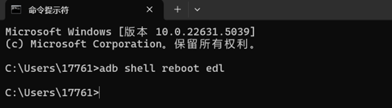
After powering on the device, use a USB-C cable to connect the computer and the device. Plug the USB-A end into the computer and the USB-C end into the device.
After connecting, execute adb devices to list the connected devices. If no device is listed, wait a moment or re-plug the USB-C cable and try again.
- Switch to flash mode by executing adb shell reboot edl.
8.2.2 Configure QFIL's Configuration Settings
- Open QFIL and click Configuration > FireHose Configuration.

- In the pop-up Download Configuration window, make the following settings:
Download Protocol: Select "0-Sahara"
Device Type: Select "ufs"
Check the "Reset After Download" option
Keep all other settings consistent with the screenshot below.
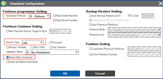
- After configuration, click OK to save.
8.2.3 Select Flash Port
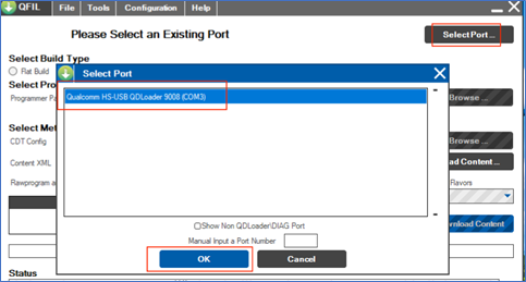
Click Select Port, and in the pop-up window, select the available 9008 port, then click OK.
After following the steps in 8.2.1 Switch to Flash Mode, the 9008 port should appear automatically. If not, power off the device, restart, and wait for the port to appear.
8.2.4 Select Build Type
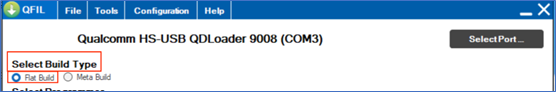
- Find the Select Build Type option and choose Flat Build.
8.2.5 Select Flash Files
Unzip the ROM file.
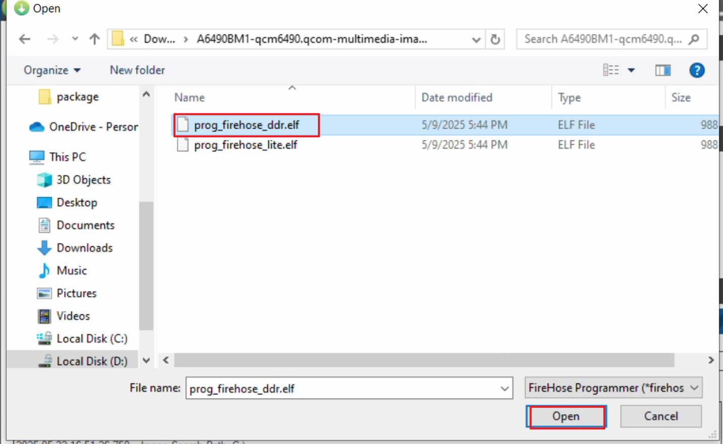
Locate Select Programmer, click Browse... next to Programmer Path, navigate to the unzipped folder, and select the ROM file.
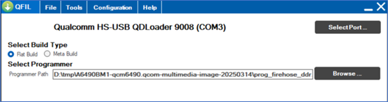
- Double-click to select prog_firehose_ddr.elf.
8.2.6 Select Flash XML File
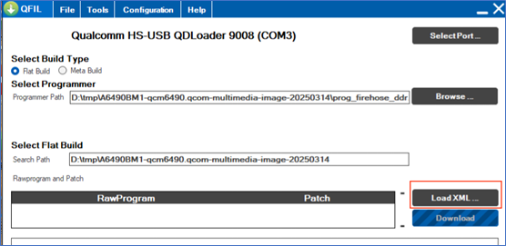
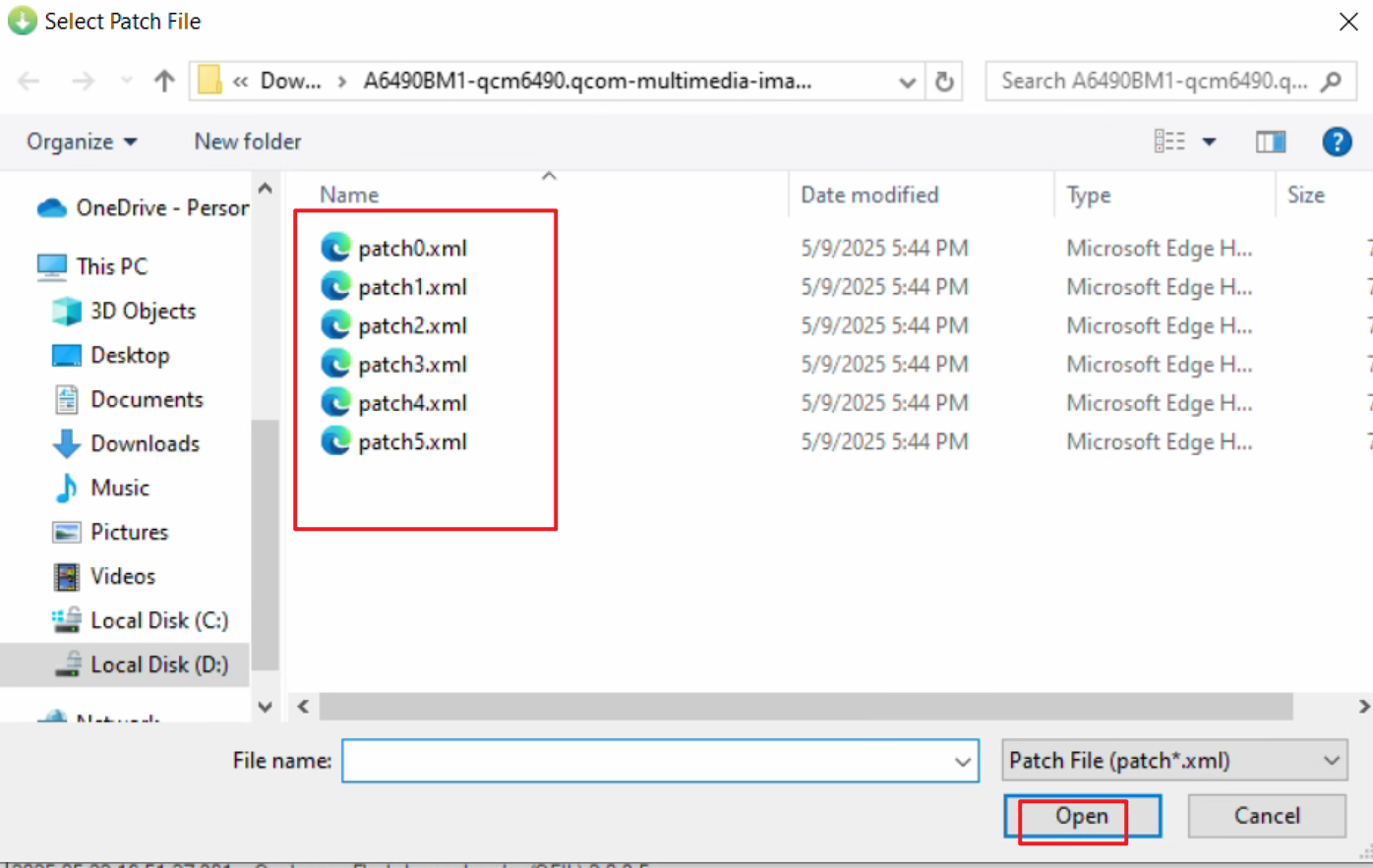
- Find Select Flat Build and click Load XML... to select the flash XML file.
- In the pop-up window, select all XML files.
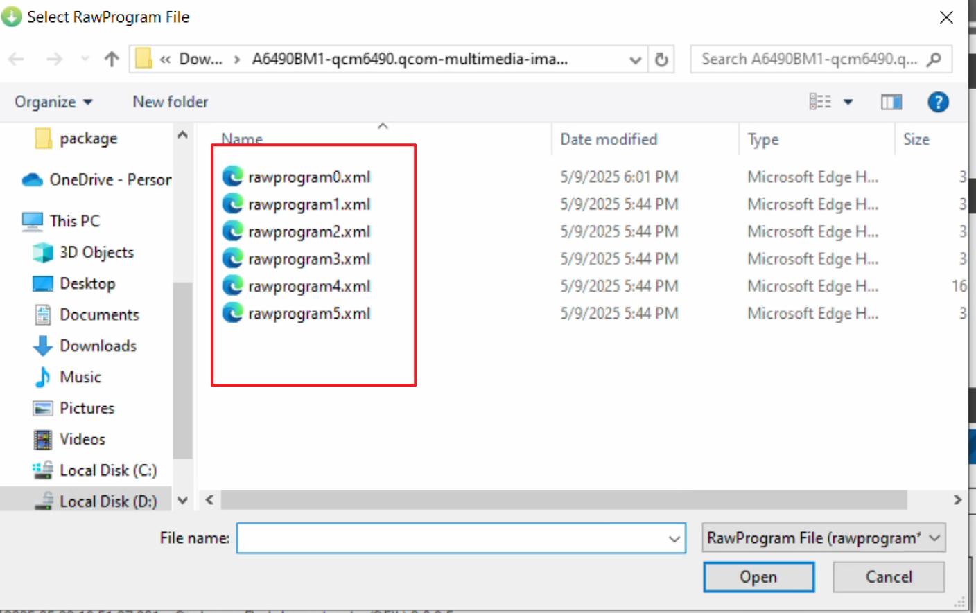
After selecting the XML file, another window will pop up automatically. Again, select all files.
8.2.7 Start Flashing
- After configuring all options, click Download to start flashing.
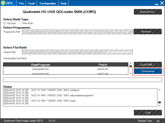
- Wait approximately 10 minutes. A "successful" message indicates the flash is complete. If flashing fails, contact APLUX after-sales support.
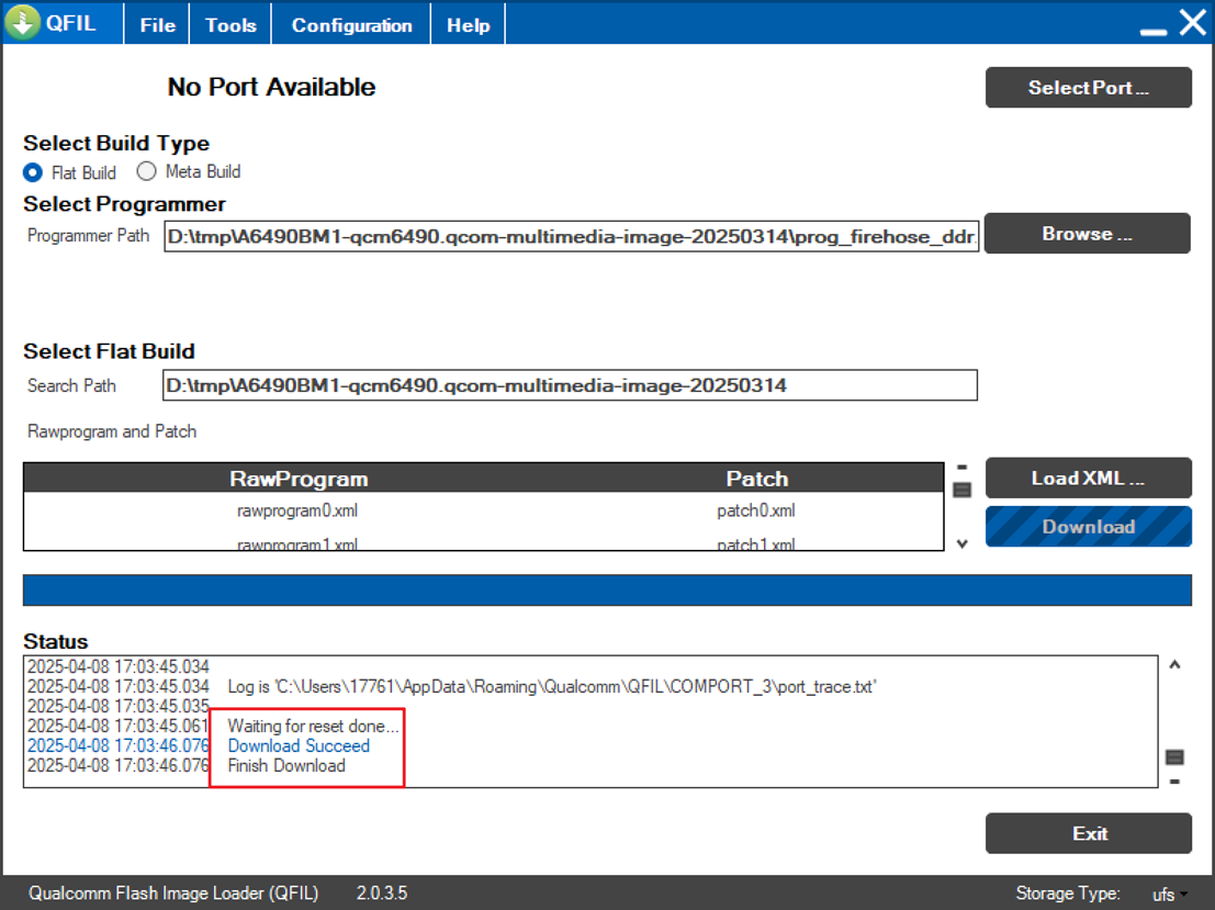
💡Tip
After flashing, wait 5 minutes for the system to initialize before use.